Hackers in Residence - Cosmic Ray Detector
Contributors:
pmm223
Circuit
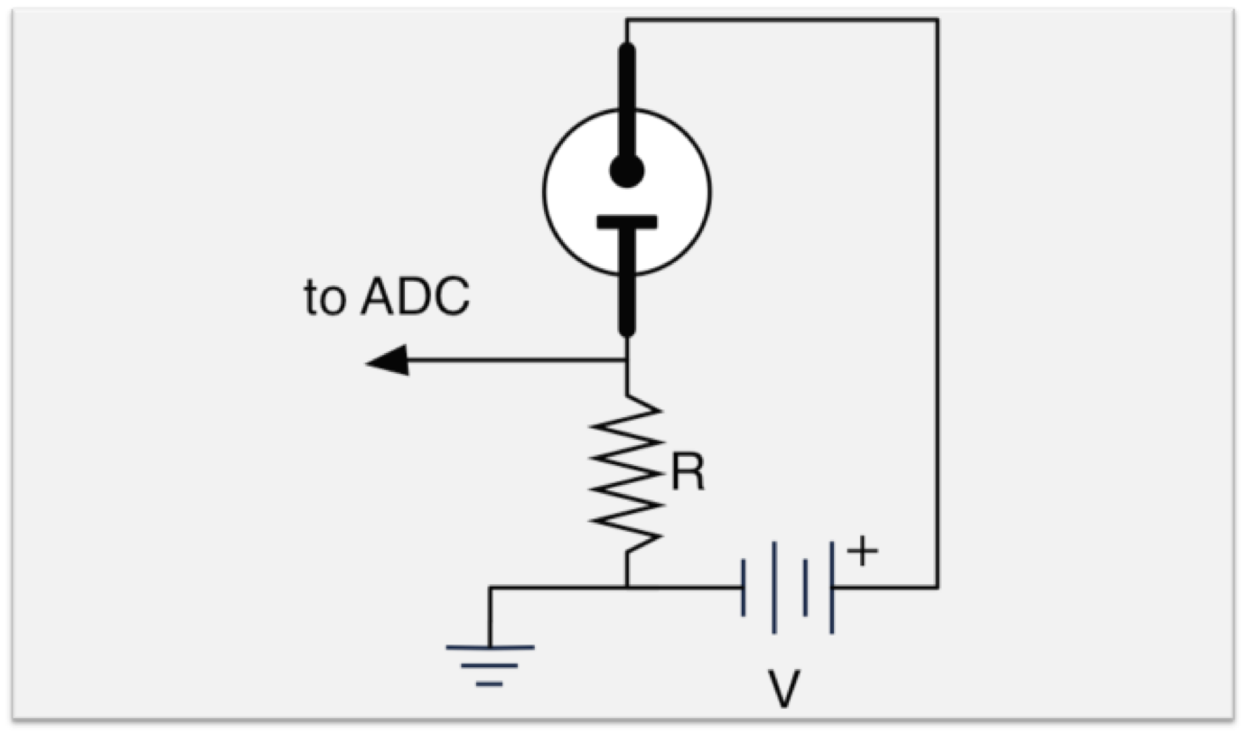
In this circuit diagram, R is the sense resistor, usually about 1 kΩ, and V is the bias voltage. The bias voltage should be less than the turn-on voltage (usually either 95 or 65 VDC depending on the type of bulb being used), but should be high enough that a cosmic ray can trigger the circuit, causing a current to flow through the resistor. This is usually about 80-94 VDC, and can be supplied by a bank of 9-volt batteries, or a DC-DC converter that has a sufficiently large capacitor across it to absorb all transients.