GPS Shield Hookup Guide
Shield Overview
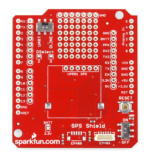
The top of the GPS shield:
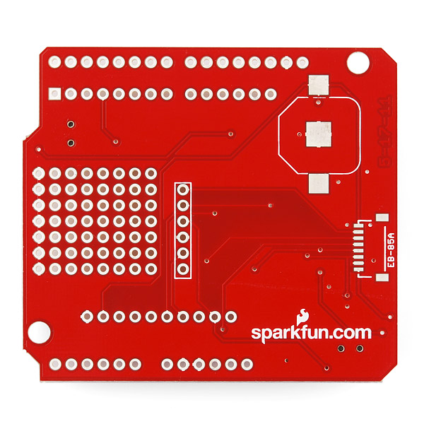
and the bottom:
The SparkFun GPS Shield includes a 6-pin JST-SH socket (labeled EM406 on the top) that fits both the EM-506 (included with the GPS shield kit) and its discontinued predecessor the EM-406A as well as the the GP-635T. There are exposed pins and a small prototyping area for use with other GPS modules. And there are unpopulated pads for the 5-pin JST-SH connector found on the discontinued EM-408 module (labeled EM408 on the top) .
The UART/DLINE switch connects the GPS module's serial lines to either Arduino hardware serial (D0/RX and D1/TX) or a user-selectable pair of software serial pins (D2 and D3 by default).
The closed solder jumpers marked Dselect 2 and 3 determine which pins are used in DLINE mode.
The ON/OFF switch controls power to the GPS module. The RESET button connects to the Arduino underneath.
On the back of the shield, there is an unpopulated 12mm coin cell battery holder footprint for adding battery backup and warm start capabilities.
There is an additional unpopulated footprint for an 8-pin JST-SH connector as seen on the discontinued 85A GPS module.
The BATT/3.3V jumper connects the VBAT lines on the unpopulated JST connectors to either the (unpopulated) backup battery or to the Arduino's 3.3V line. 3.3V is selected by default.

