GPS-RTK2 Hookup Guide
Hardware Overview
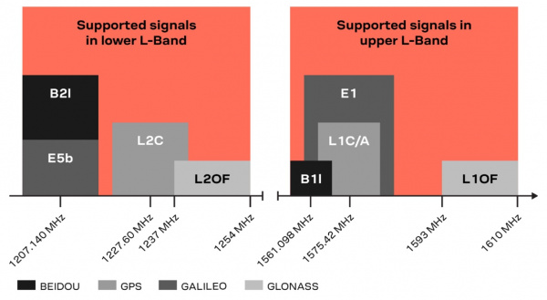
One of the key differentiators between the ZED-F9P and almost all other low-cost RTK solutions is the ZED-F9P is capable of receiving both L1 and L2 bands.
Communication Ports
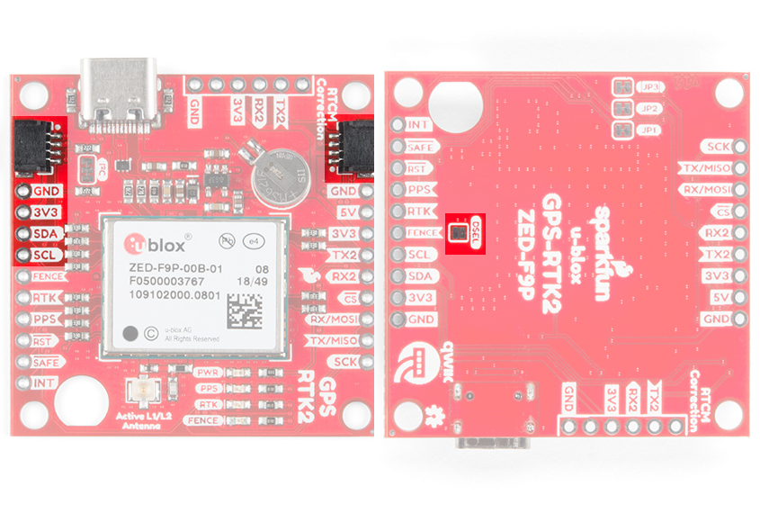
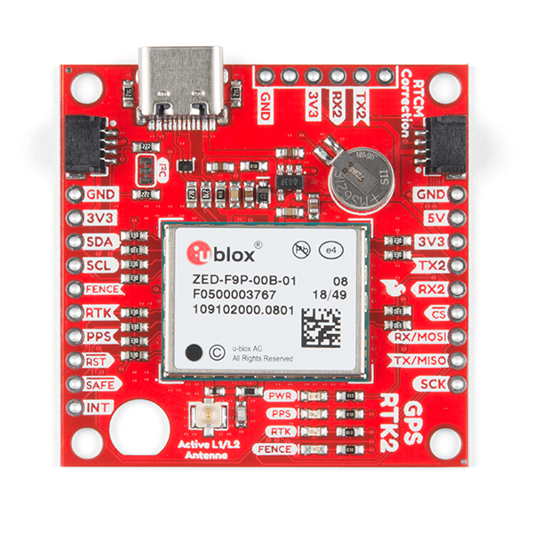
The ZED-F9P is unique in that it has five communication ports which are all active simultaneously. You can read NMEA data over I2C while you send configuration commands over the UART and vice/versa. The only limit is that the SPI pins are mapped onto the I2C and UART pins so it’s either SPI or I2C+UART. The USB port is available at all times.
 |
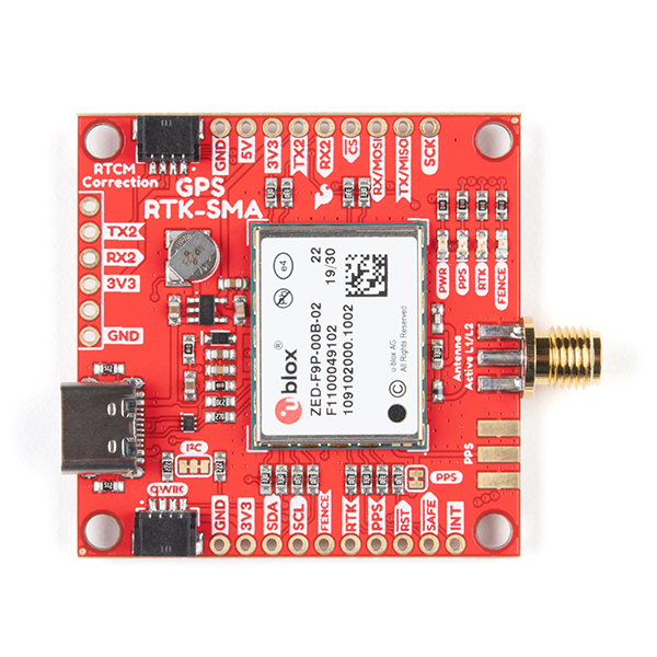 |
| SparkFun GPS-RTK2 Board | SparkFun GPS-RTK-SMA Board |
USB
The USB C connector makes it easy to connect the ZED-F9P to u-center for configuration and quick viewing of NMEA sentences. It is also possible to connect a Raspberry Pi or other single board computer over USB. The ZED-F9P enumerates as a serial COM port and it is a separate serial port from the UART interface. See Getting Started with U-Center for more information about getting the USB port to be a serial COM port.
 |
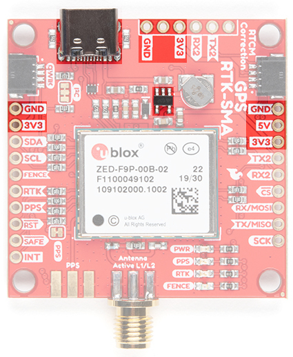 |
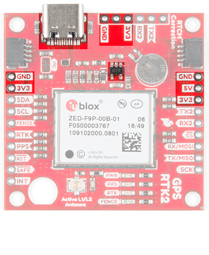
| The USB port and power GPS-RTK2 | The USB port and power GPS RTK-SMA |
A 3.3V regulator is provided to regulate the 5V USB down to 3.3V the module requires. External 5V can be applied or a direct feed of 3.3V can be provided. Note that if you’re provide the board with 3.3V directly it should be a clean supply with minimal noise (less than 50mV VPP ripple is ideal for precision locating).
The 3.3V regulator is capable of sourcing 600mA from a 5V input and the USB C connection is capable of sourcing 2A.
I2C (a.k.a DDC)
The u-blox ZED-F9P has a “DDC” port which is really just an I2C port (without all the fuss of trademark issues). These pins are shared with the SPI pins. By default, the I2C pins are enabled. Be sure the DSEL jumper on the rear of the board is open. The GPS-RTK2 and GPS-RTK-SMA from SparkFun also includes two Qwiic connectors to make daisy chaining this GPS receiver with a large variety of I2C devices. Checkout Qwiic for your next project.
All features are accessible over the I2C ports including reading NMEA sentences, sending UBX configuration strings, piping RTCM data into the module, etc. We’ve written an extensive Arduino library showing how to configure most aspects of the ZED-F9P making I2C our preferred communication method on the ZED. You can get the library through the Arduino library manager by searching ‘SparkFun u-blox GNSS’. Checkout the SparkFun u-blox Library section for more information.
UART/Serial
The classic serial pins are available on the ZED-F9P but are shared with the SPI pins. By default, the UART pins are enabled. Be sure the DSEL jumper on the rear of the board is open.
- TX/MISO = TX out from ZED-F9P
- RX/MOSI = RX into ZED-F9P
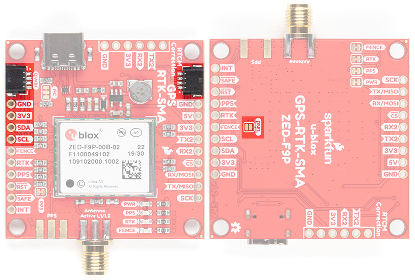
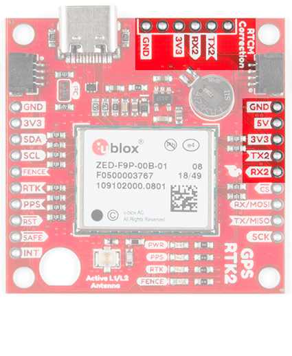
There is a second serial port (UART2) available on the ZED-F9P that is primarily used for RTCM3 correction data. By default, this port will automatically receive and parse incoming RTCM3 strings enabling RTK mode on the board. In addition to the TX2/RX2 pins we have added an additional ‘RTCM Correction’ port where we arranged the pins to match the industry standard serial connection (aka the 'FTDI' pinout). This pinout is compatible with our BlueSMiRF v2 and Serial Basic so you can send RTCM correction data from a cell phone or computer. Note that RTCM3 data can also be sent over I2C, UART1, SPI, or USB if desired.
 |
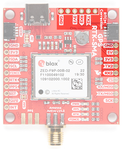 |
| UART2 and RTCM Correction Port on the GPS-RTK2 | UART2 and RTCM Correction Port on the GPS-RTK-SMA |
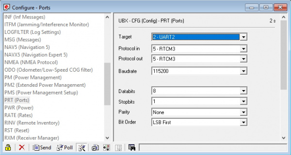
The RTCM correction port (UART2) defaults to 38400bps serial but can be configured via software commands (checkout our Arduino library) or over USB using u-center. Keep in mind our BlueSMiRF defaults to 115200bps. If you plan to use Bluetooth for correction data (we found it to be easiest), we recommend you increase this port speed to 115200bps using u-center. Additionally, but less often needed, the UART2 can be configured for NMEA output. In general, we don’t use UART2 for anything but RTCM correction data, so we recommend leaving the in/out protocols as RTCM.
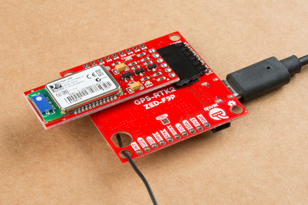
If you’ve got the ZED-F9P setup for base station mode (also called survey-in mode) the UART2 will output RTCM3 correction data. This means you can connect a radio or wired link to UART2 and the board will automatically send just RTCM bytes over the link (no NMEA data taking up bandwidth). Here is an example using the RTK2 but you can also use the RTK-SMA using the same setup.
SPI
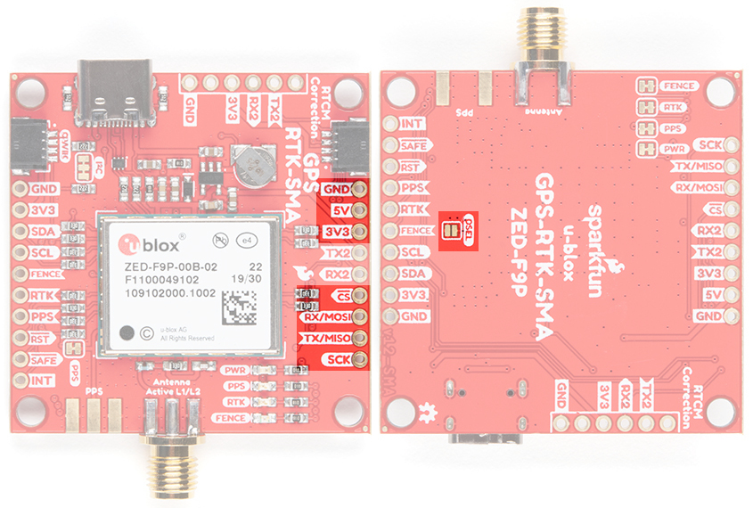
The ZED-F9P can also be configured for SPI communication. By default, the SPI port is disabled. To enable SPI close the DSEL jumper on the rear of the board. Closing this jumper will disable the UART1 and I2C interfaces (UART2 will continue to operate as normal).
Control Pins
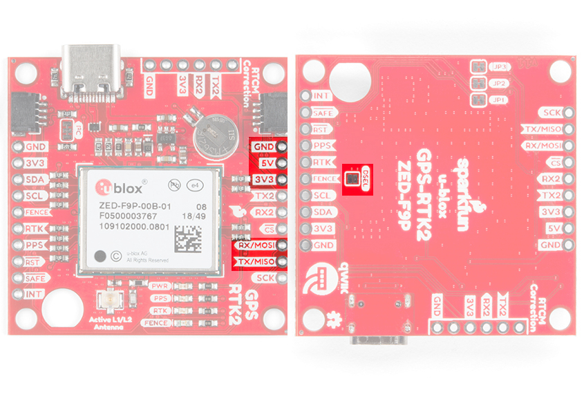
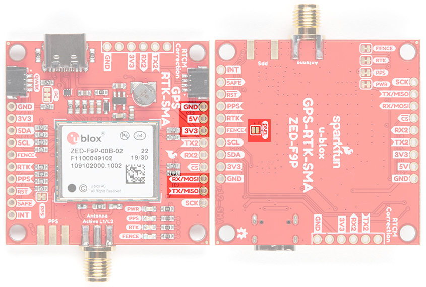
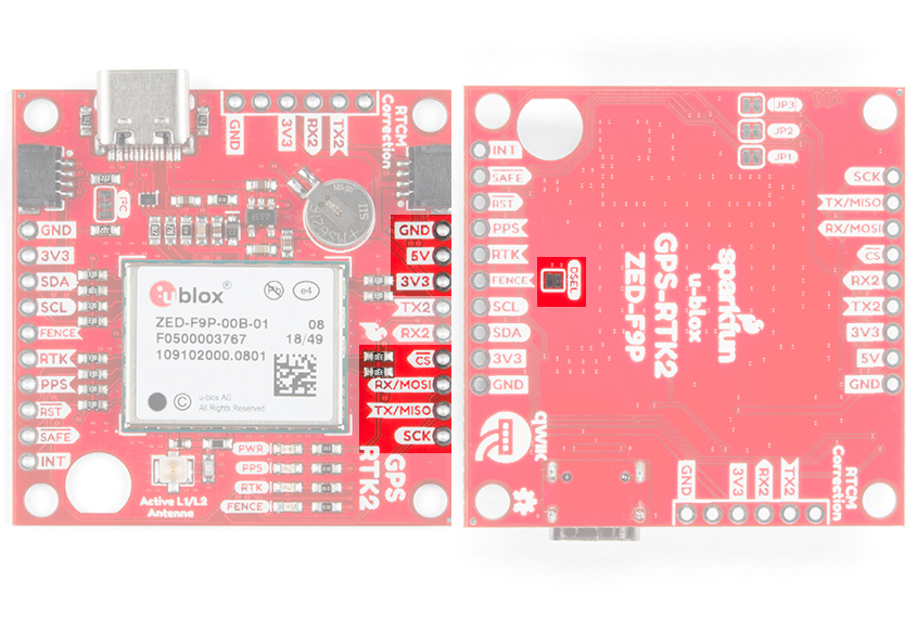
The control pins are highlighted below.
 |
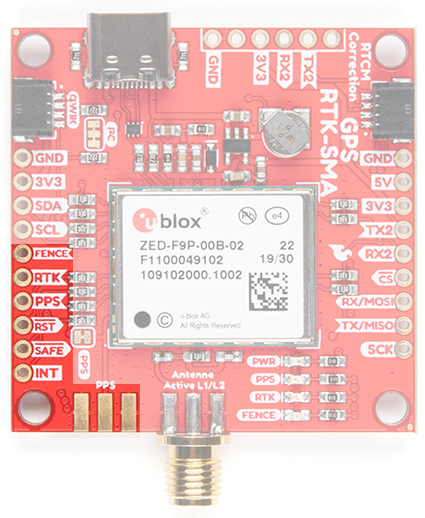 |
| Highlighted control pins of the SparkFun GPS-RTK2 | Highlighted control pins of the SparkFun GPS-RTK-SMA |
These pins are used for various extra control of the ZED-F9P:
- FENCE: Geofence output pin. Configured with U-Center. Will go high or low when a geofence is setup. Useful for triggering alarms and actions when the module exits a programmed perimeter.
- RTK: Real Time Kinematic output pin. Remains high when module is in normal GPS mode. Begins blinking when RTCM corrections are received and module enters RTK float mode. Goes low when module enters RTK fixed mode and begins outputting cm-level accurate locations.
PPS: Pulse-per-second output pin. Begins blinking at 1Hz when module gets basic GPS/GNSS position lock.
RST: Reset input pin. Pull this line low to reset the module.
- SAFE: Safeboot input pin. This is required for firmware updates to the module and generally should not be used or connected.
- INT: Interrupt input/output pin. Can be configured using U-Center to bring the module out of deep sleep or to output an interrupt for various module states.
Antenna
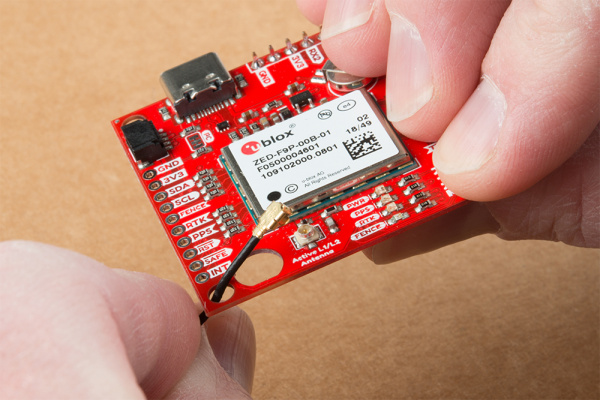
The ZED-F9P requires a good quality GPS or GNSS (preferred) antenna. A U.FL connector is provided. Note: U.FL connectors are rated for only a few mating cycles (about 30) so we recommend you set it and forget it. You may need to secure the u.FL to SMA cable depending on your application. Otherwise, you could use the RTK-SMA version.
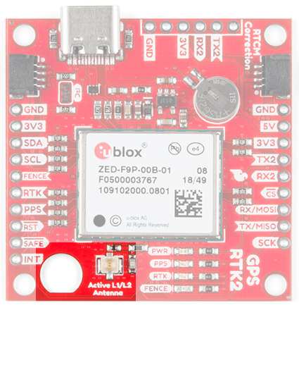 |
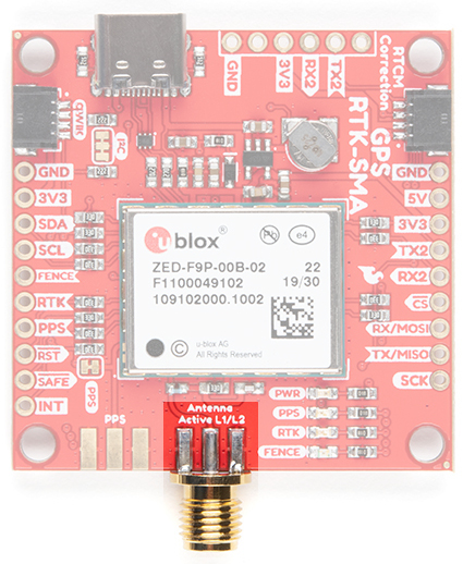 |
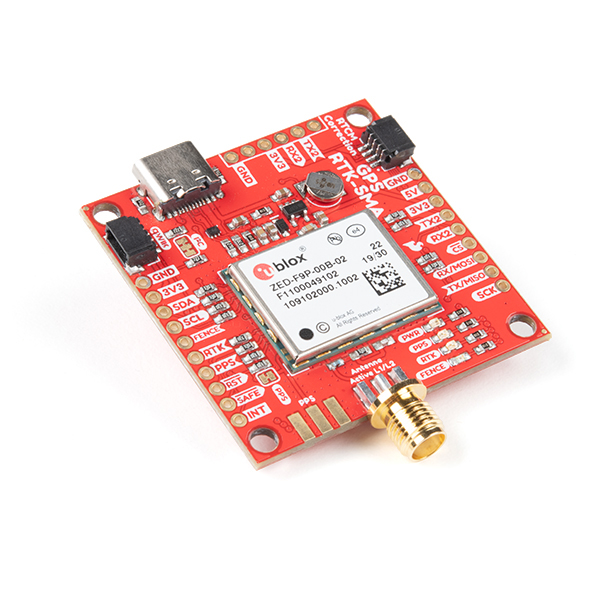
| U.FL antenna connector and SMA cut-out on the GPS RTK2 | SMA antenna connector on the GPS-SMA |
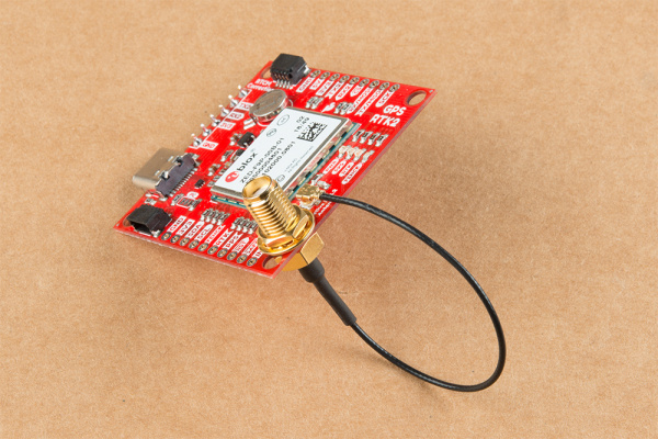
A cutout for the SMA bulkhead is available for those who want an extra sturdy connection. We recommended installing the SMA into the board only when the board is mounted in an enclosure. Otherwise, the cable runs the risk of being damaged when compressed (for example, students carrying the board loose in a backpack). ac
A U.FL to SMA cable threaded through the mounting hole provides a robust connection that is also easy to disconnect at the SMA connection if needed. Check below in Connecting an Antenna for more information.
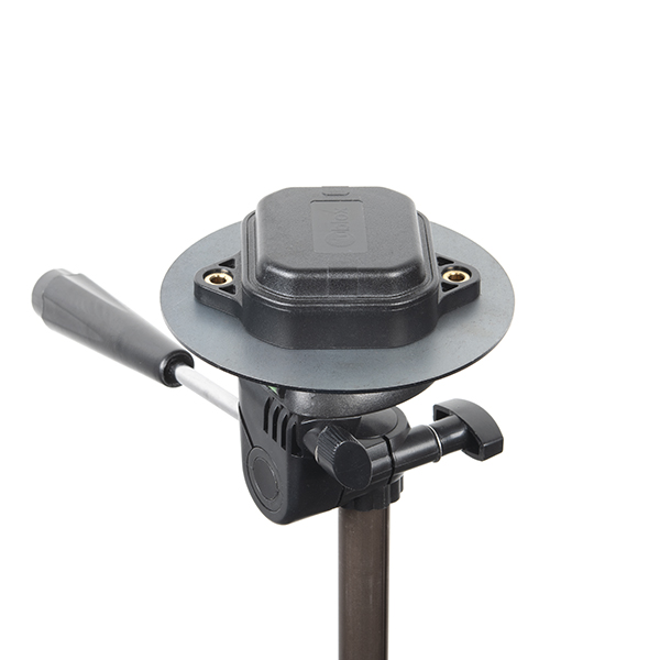
Low-cost magnetic GPS/GNSS antennas can be used (checkout the u-blox white paper) but a 4” / 10cm metal disc is required to be placed under the antenna as a metal ground plane.
LEDs
The board includes four status LEDs as indicated in the image below.
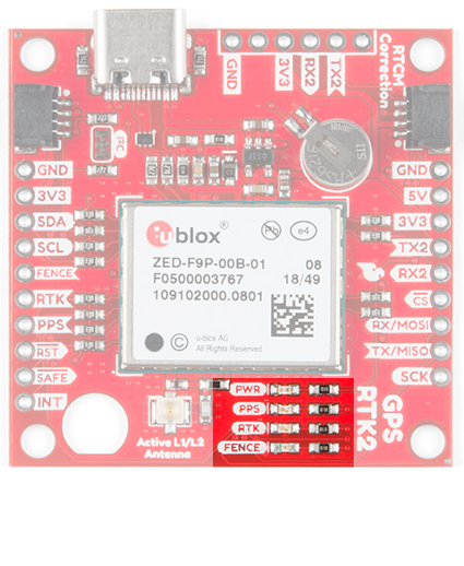 |
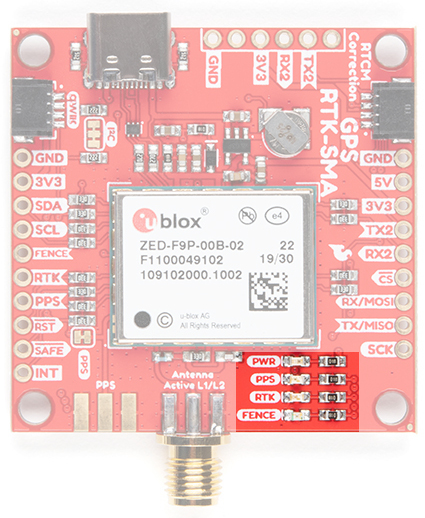 |
| Status LEDs on the GPS-RTK2 | Status LEDs on the GPS-SMA |
- PWR: The power LED will illuminate when 3.3V is activated either over USB or via the Qwiic bus.
- PPS: The pulse per second LED will illuminate each second once a position lock has been achieved.
- RTK: The RTK LED will be illuminated constantly upon power up. Once RTCM data has been successfully received it will begin to blink. This is a good way to see if the ZED-F9P is getting RTCM from various sources. Once an RTK fix is obtained, the LED will turn off.
- FENCE: The FENCE LED can be configured to turn on/off for geofencing applications.
Jumpers
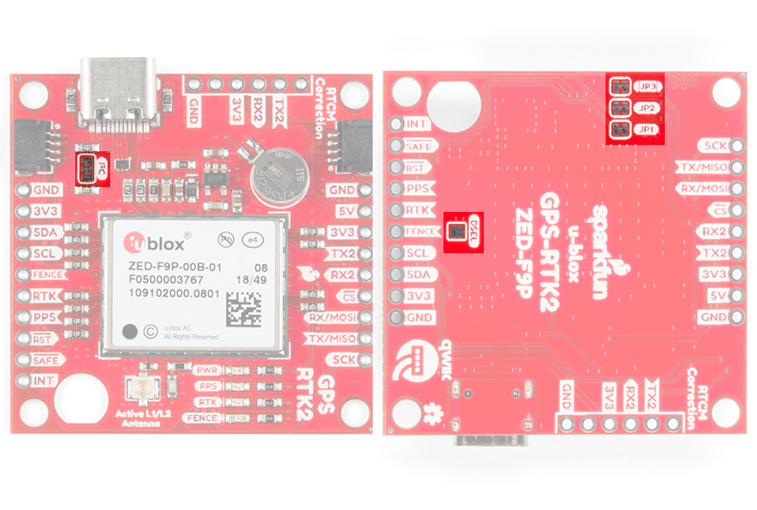
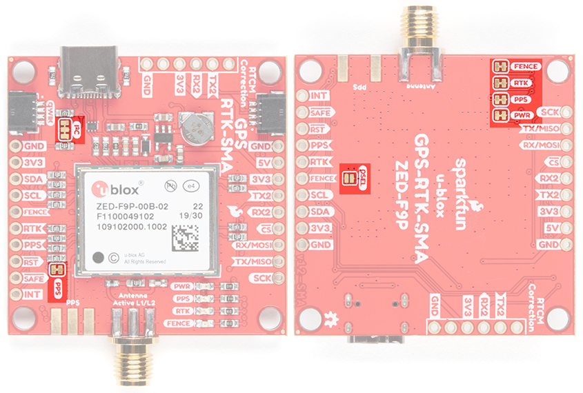
There are five jumpers used to configure the GPS-RTK2.
Closing DSEL with solder enables the SPI interface and disables the UART and I2C interfaces. USB will still function.
Cutting the I2C jumper will remove the 2.2k Ohm resistors from the I2C bus. If you have many devices on your I2C bus you may want to remove these jumpers. Not sure how to cut a jumper? Read here!
Cutting the JP1, JP2, JP3 jumpers on the RTK2 will disconnect of the various status LEDs from their associated pins. These have been labeled on the RTK-SMA version. We have included a jumper for the PPS on the top and bottom of the RTK-SMA.
Backup Battery
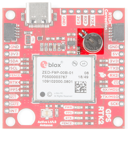
The MS621FE rechargeable battery maintains the battery backed RAM (BBR) on the GNSS module. This allows for much faster position locks (a.k.a. hot start). The BBR is also used for module configuration retention. The battery is automatically trickle charged when power is applied and should maintain settings and GNSS orbit data for up to two weeks without power.
 |
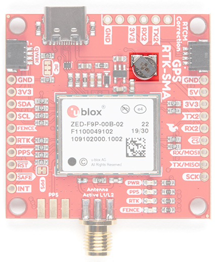 |
| The backup battery on the SparkFun RTK2 | The backup battery on the SparkFun RTK-SMA |
Connecting an Antenna
U.FL connectors are very good but they are a designed to be implemented inside a small embedded application like a laptop. Exposing a U.FL connector to the wild risks it getting damaged. To prevent damaging the U.FL connection on the GPS-RTK2 we recommend threading the U.FL cable through the stand-off hole, then attach the U.FL connectors. This will provide a great stress relief for the antenna connection. Now attach your SMA antenna of choice.
Three Quick Tips About Using U.FL
Additionally, a bulkhead cut-out is provided to screw the SMA onto the PCB if desired.
While this method decreases stress from the U.FL connector it is only recommended when the board has been permanently mounted. If the board is not mounted, the cable on the U.FL cable is susceptible to being kinked causing impedance changes that may decrease reception quality.
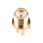
If you are using the the RTK-SMA, there is no need to worry about this since there is a SMA connector soldered on the board providing a sturdy connection.
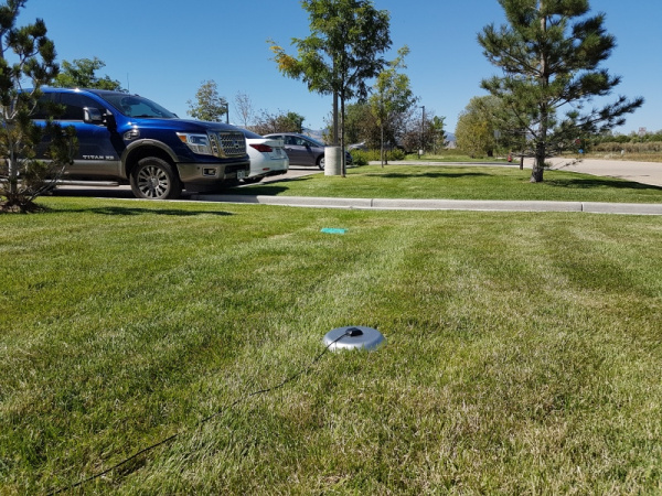
If you’re indoors you must run a SMA extension cable long enough to locate the antenna where it has a clear view of the sky. That means no trees, buildings, walls, vehicles, or concrete metally things between the antenna and the sky. Be sure to mount the antenna on a 4”/10cm metal ground plate to increase reception.
Board Dimensions
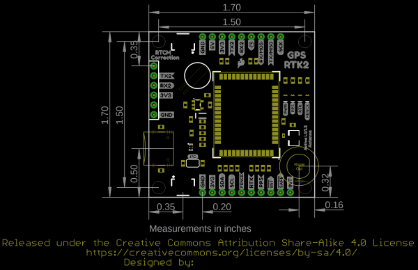
The overall board dimensions for each board is ~1.70" x ~1.70" (~43.18mm x ~43.18mm). Keep in mind the connectors are not flush with the board, which adds additional length to the board. Make sure to take that into account when mounting and placing the board in an enclosure.
 |
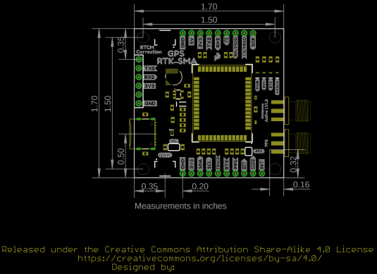 |
| Board Dimensions for RTK2 | Board Dimensions for RTK-SMA |
