Getting Started with 3D Printing Using Tinkercad
Taking Measurements
The advantage of 3D printing your project enclosure is that you get to make it the exact size of your project! You're also able to add any features, such as mounting holes and side ports to access USB, power, etc.
To start, lay your parts (electronics, motors, switches, etc.) on a flat surface, and orient them in a way that you think is the most space efficient. For this tutorial, we'll create a box that fits the Arduino Pro Mini, but you can modify the dimensions to fit your own project. Use a ruler or set of calipers to measure the outer dimensions of your project (also known as the "footprint"). This is the minimum amount of area we'll need in the base of the box.
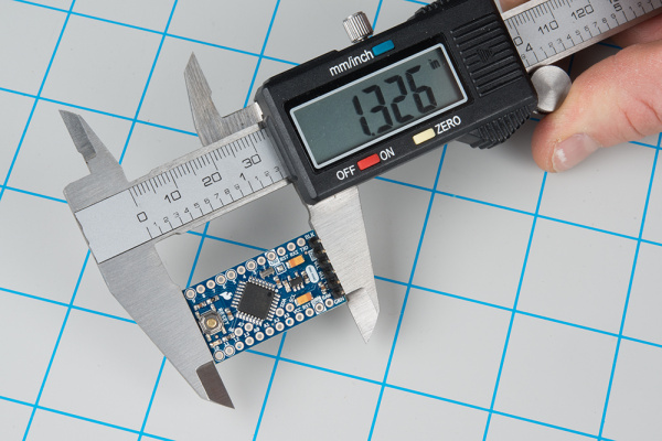
Let's start by measuring the length (remember, this can be anything: a collection of PCBs, candy, your perpetual motion machine, etc.).
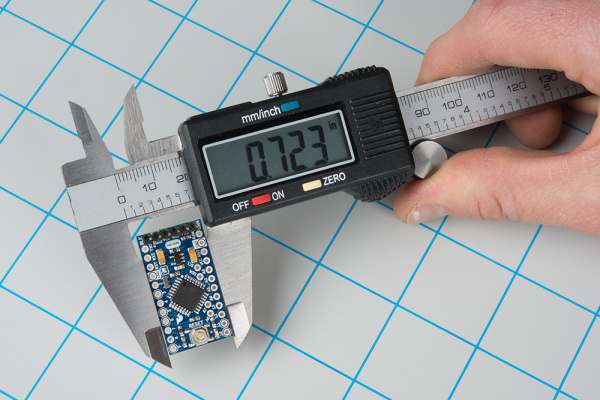
Then, let's measure the width of the board.
The electronics portion of the project (just the Pro Mini in this example) has a footprint of 1.326 x 0.723 inches. This guide shows things in inches, as most of the SparkFun boards were created with the Imperial system. Feel free to change to Metric. Next, we want to measure the maximum height of the pieces to be enclosed.
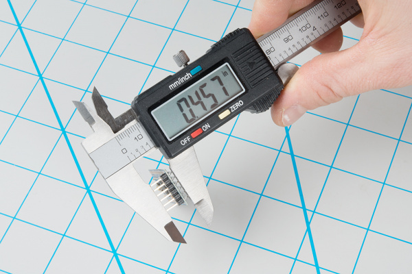
As you can see, the maximum height of the Pro Mini (with headers) is 0.457 inches.
We'll want to round up our measurements to allow for some wiggle room in the enclosure. For this example project, we'll use the following dimensions for the required cavity size:
- Length: 1.4 inches
- Width: 0.8 inches
- Height: 0.5 inches
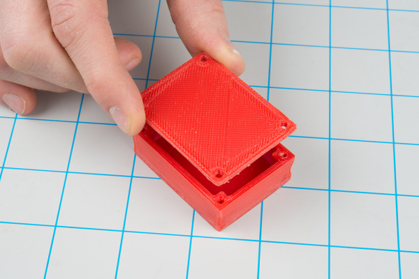
To attach a lid to our enclosure, we'll want to add some screw holes to the box as well as create a lid with similarly placed holes. We'll print both of these items at the same time.
There are several ways to attach screws to a 3D printed object. One of the most robust methods is to use heat-set inserts. You can use use a soldering iron to push these into an opening, which melts the plastic. Once it cools, the insert will be firmly embedded in the plastic, and you can use them as screw taps.
For our quick-and-easy enclosure, we'll just make holes slightly smaller than the screw size so that the thread bites into the plastic. It won't hold as well as a heat-set insert, but it should be good enough for prototyping purposes. Ideally, you will want self-tapping screws intended for plastic, but machine screws will work in a pinch.
For more information on how to join 3D printed parts using screws/bolts, including heat-set inserts, see this article.
We'll be using #4-40 screws to affix the lid to the enclosure. As a result, we'll want to look up the sizes of the holes we'll need. Take a look at this tap and drill size chart from Michigan Tech. You can see that for a #4-40 screw, we'll need to drill a hole with a diameter of 0.0890 inches (tap drill size) for the screw's threads to bite into the material. These holes will be put into the base of the enclosure. For the lid, we'll want the screws to be able to freely spin, so we'll use the free fit drill size, which is 0.1285 inches.
Most fused filament fabrication (FFF) 3D printers, like our LulzBot, do not have great tolerances or resolution (e.g. down to the 0.001 inch). The molten plastic that comes out of the extruder also has a habit of "melting" a bit around the edges, which can cause holes to shrink. In addition, using self-tapping screws forces some of the material to move out of the way, which can cause stress and fractures in the plastic. As a result, we'll need to oversize the drill holes by 0.01 to 0.02 inches.
Read the tap drill size and the free fit size from the chart, round up, and oversize it by about 0.01 inch:
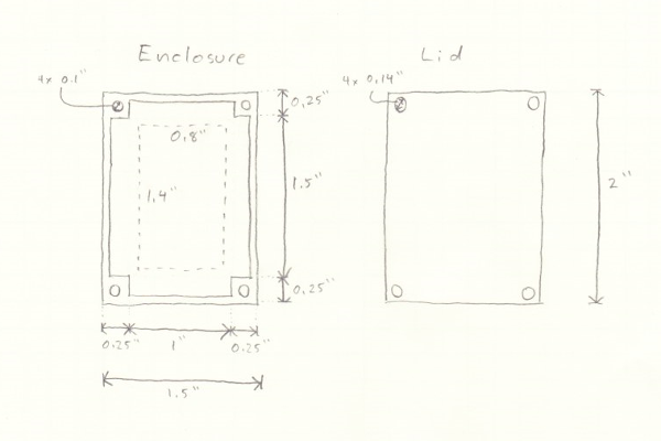
- Enclosure screw hole (tap): 0.0890 inches → 0.100 inches
- Lid screw hole (free fit): 0.1285 inches → 0.140 inches
From here, it can help to sketch out what we want the enclosure and lid to look like. Adding dimensions will help us when we go to model it in the next section. Just to give us even more room, let's round up the required cavity space to the nearest 0.5 inches. Because the posts in the corners (that hold the screws) are each 0.25 x 0.25 inches, this will make our entire enclosure's footprint come out nicely to 2.0 x 1.5 inches.
We'll use these dimensions in the next section to model the box in Tinkercad.
