Getting Started with 3D Printing Using Tinkercad
 Shawn Hymel,
  Feldi
Feldi 
Modeling in Tinkercad
Create a New Design
Navigate to tinkercad.com, and sign up for a new account (if you don't have one already).
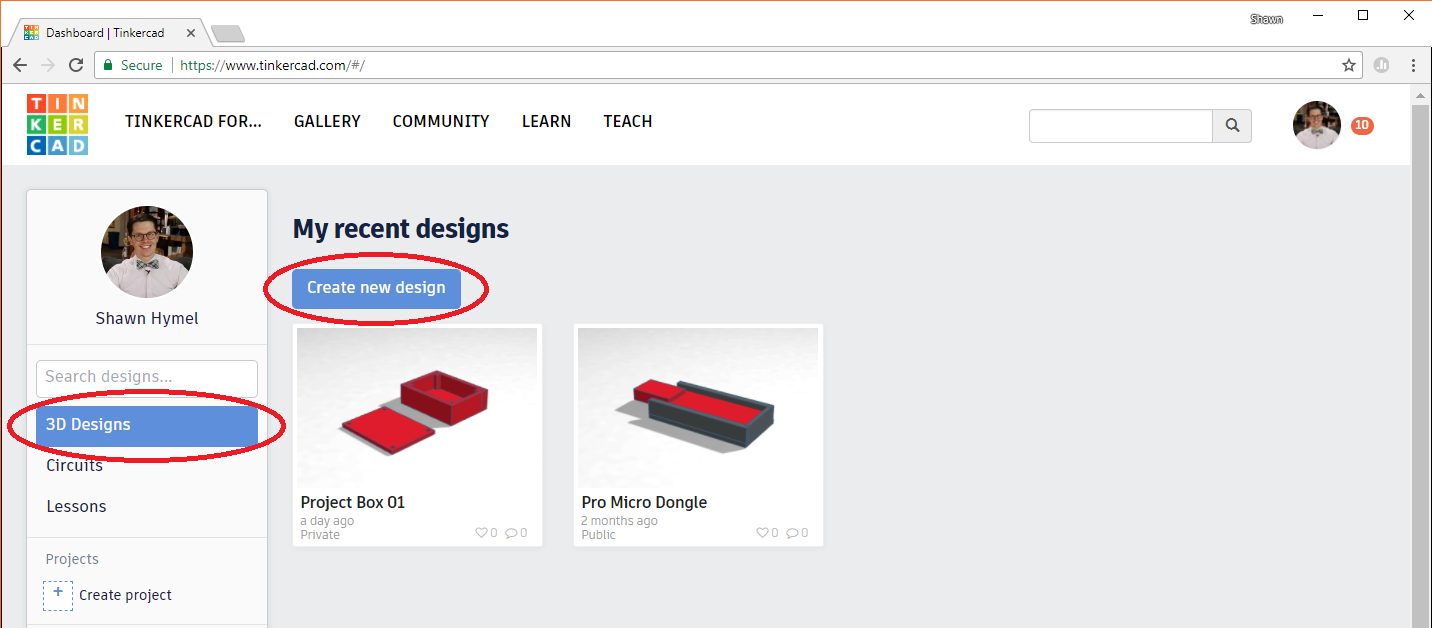
Once you've logged in, make sure 3D Designs is selected on the left and click Create new design.
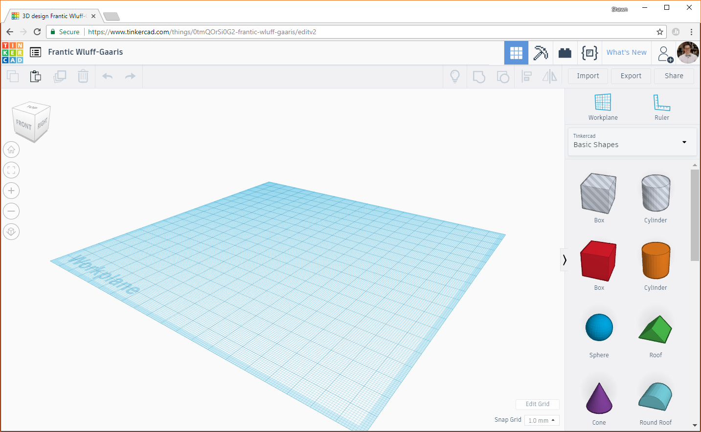
You'll be presented with a blank workplane and a number of shapes on the right side. The basics of Tinkercad are simple: you drag a shape onto the workplane, modify it, and combine it with other shapes. If you right-click and drag on the workplane, it will rotate. If you middle-click and drag on the workplane, it will pan. Try playing around with rotating and panning your workplane to get a feel for how it works.
We'll want to work in inches for this project, so click Edit Grid in the bottom right of the Tinkercad window. You should get a pop-up with some options. Change Units to Inches.
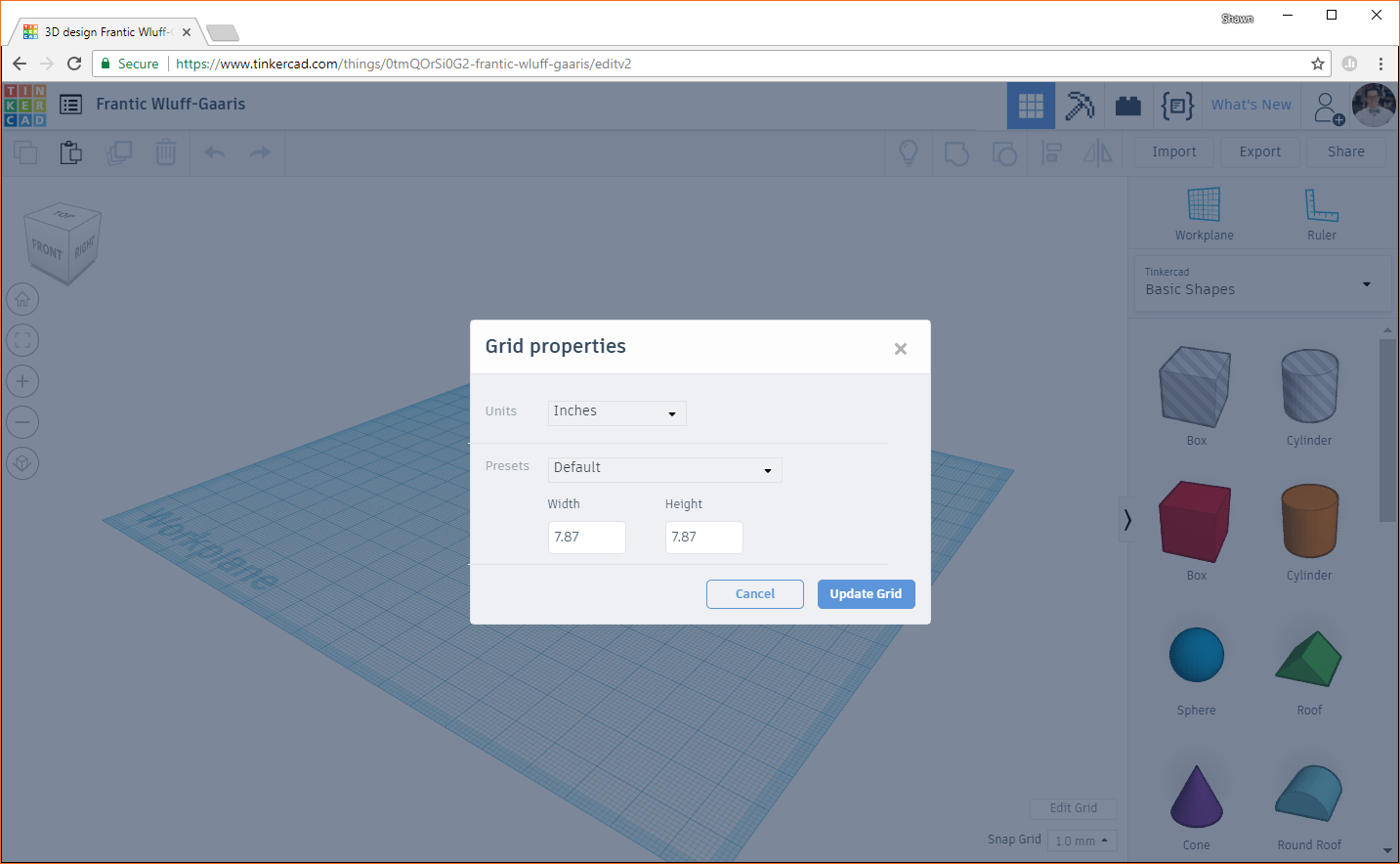
Click Update Grid. At the top left, you should see the name of your project, which should have been given some random sequence of words (for example, mine was named "Fantic Wluff-Gaaris"). You can click on the name and change it to anything you'd like. I'll keep mine as Fantic Wluff-Gaaris because it's awesome (albeit not terribly descriptive).
Lay the Foundation
Click on the red box (from the list of shapes on the right side), and drag it to somewhere near the middle of the workplane. Note that everything we do is relative to the workplane, and we can move the workplane to make things easier (which we'll do in a future step).
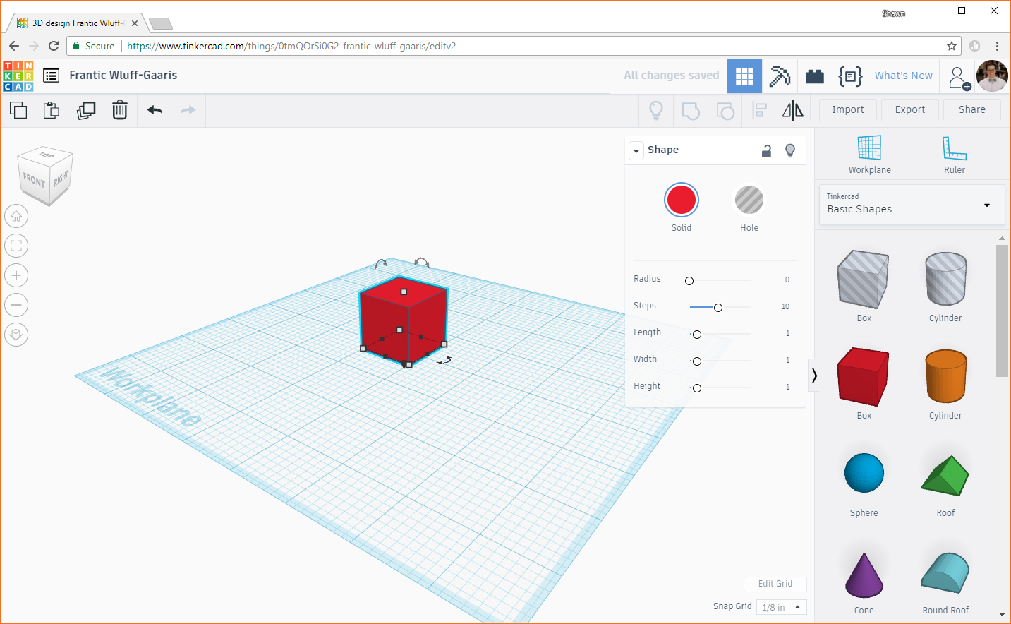
Zoom in on the box using the buttons on the left side (or your mouse wheel). Rotate and pan the workplane as necessary to get a good view of your box. With the box selected, click on the red color swatch above the word Solid on the object properties window. From there, you can select the color of your box. No, it won't affect the color of the print (that comes from the color of the filament that we'll choose), but it might make your 3D model easier to see in Tinkercad. I'll leave mine as red; it's a good color.

Click on one of the corners (gray squares), and you should see the footprint dimensions of the box appear on the workplane (you can see that the footprint of the box is 1 x 1 inches).
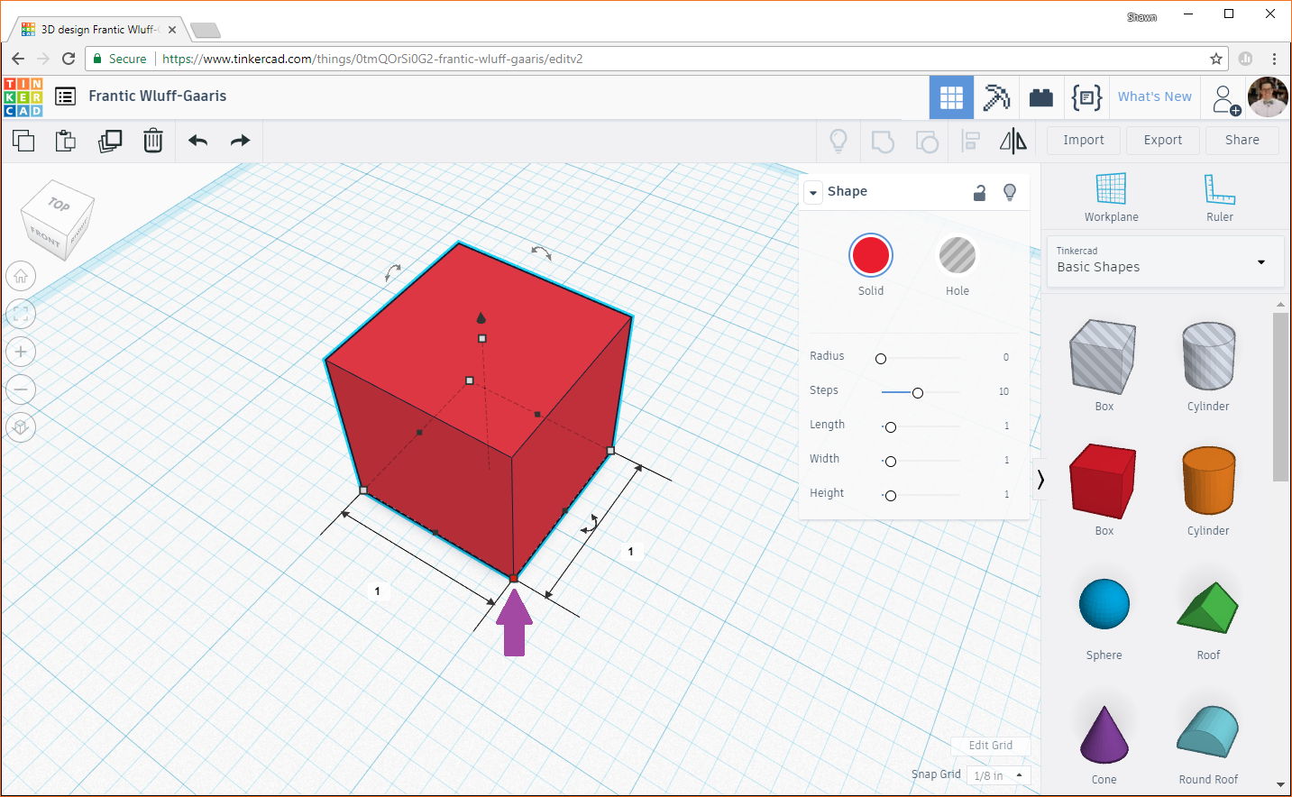
Click on one of the dimensions to edit it.
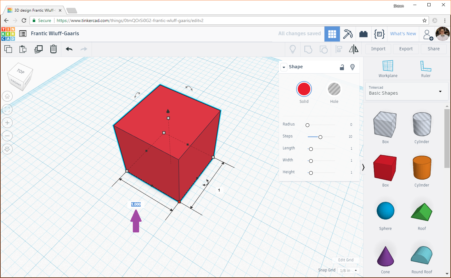
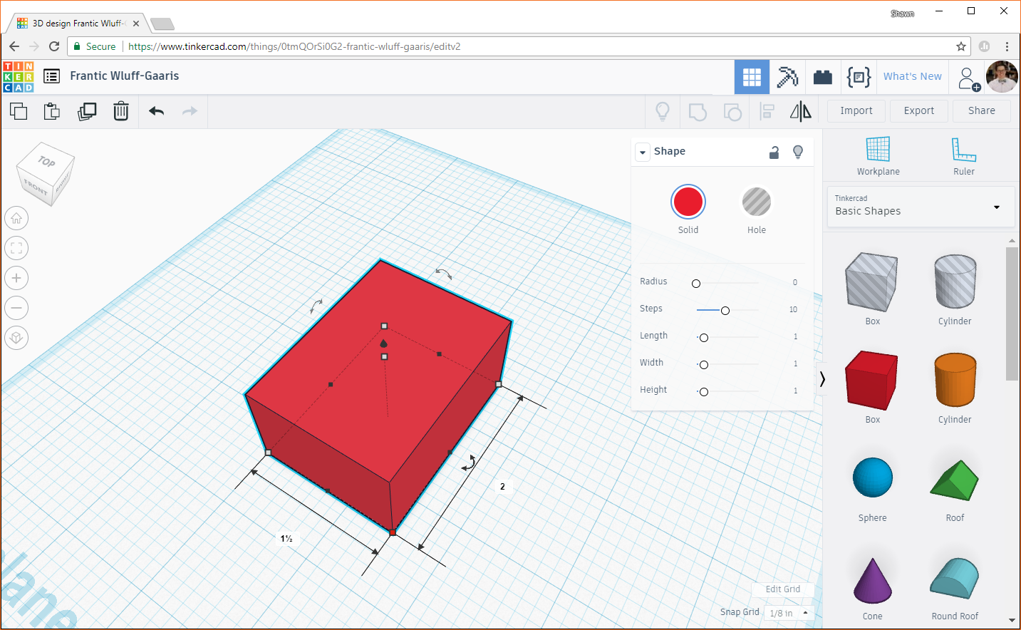
We'll make this dimension the width of the enclosure, so type 1.5 and press enter. Click on the other dimension (the length, in our case), and enter 2.0. Your cube should turn into a rectangular box.
Click on the height node (gray box in the middle of the top of your box object). This will display the height (in inches) of your box.

Click on the dimension (1 in this case) and change it to 0.1. In my experience, 0.1 inches is a good thickness for walls for an enclosure like this. Any thinner, and they become quite flimsy.

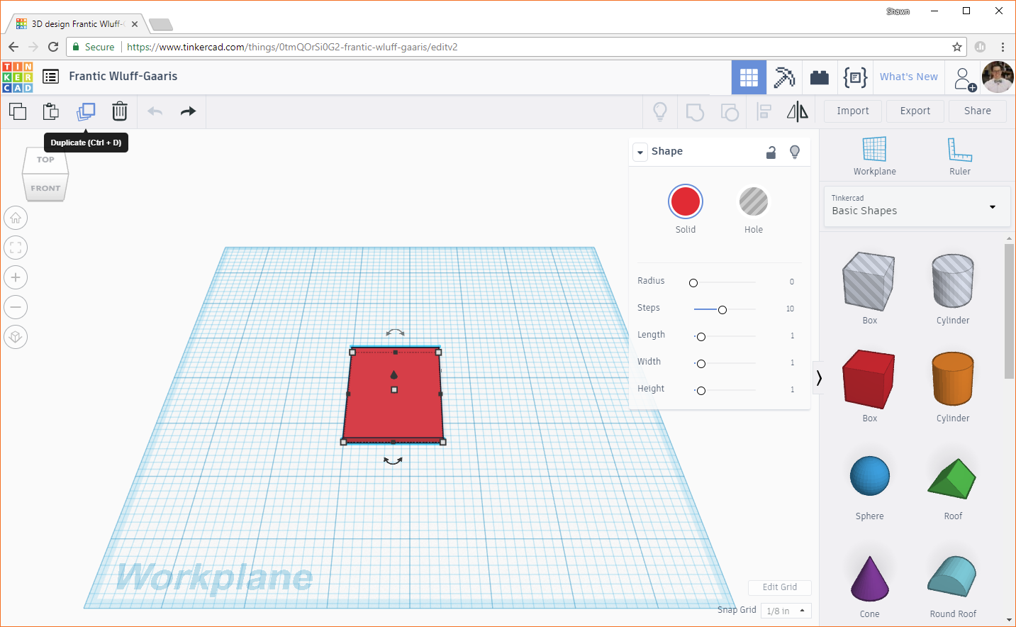
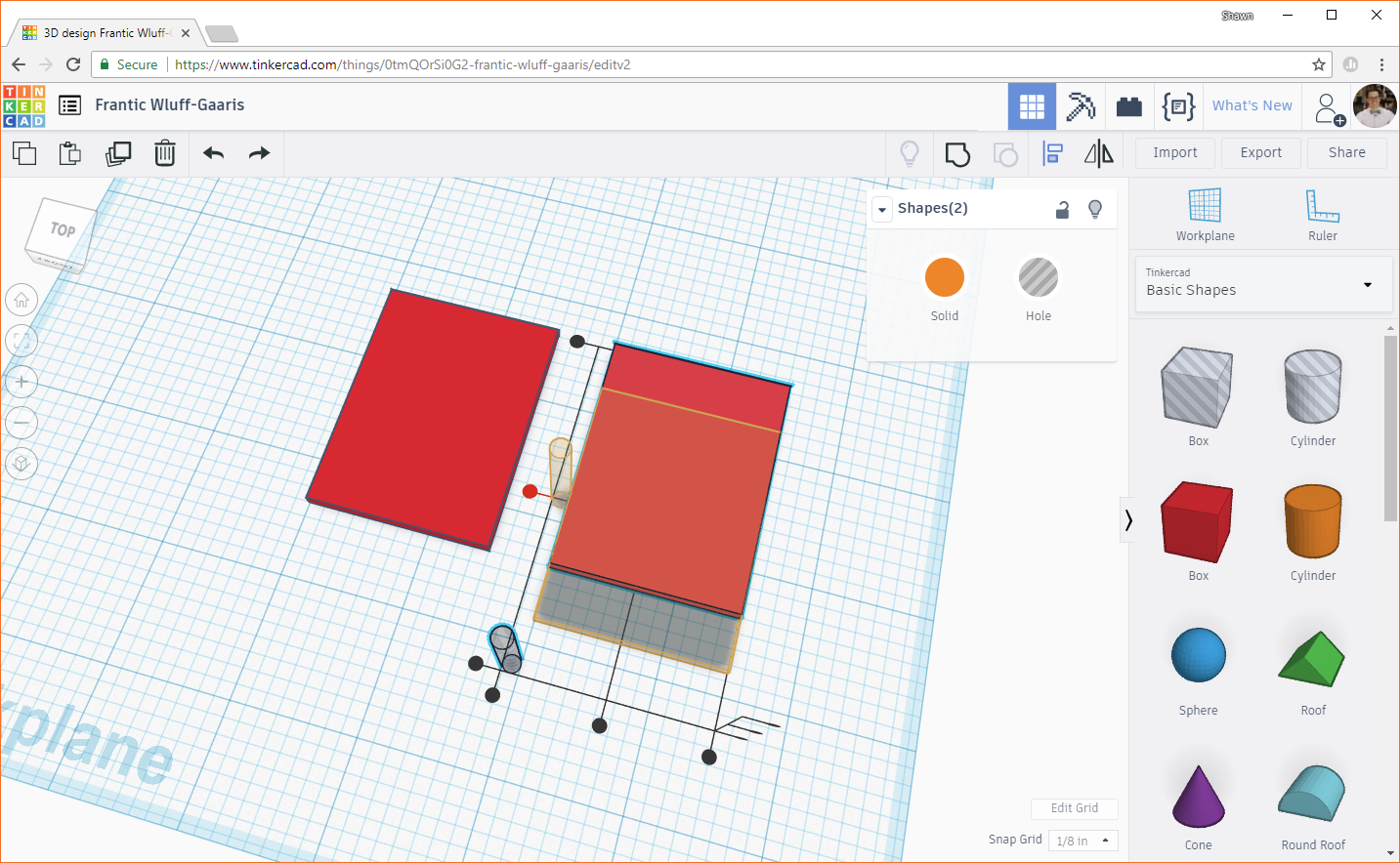
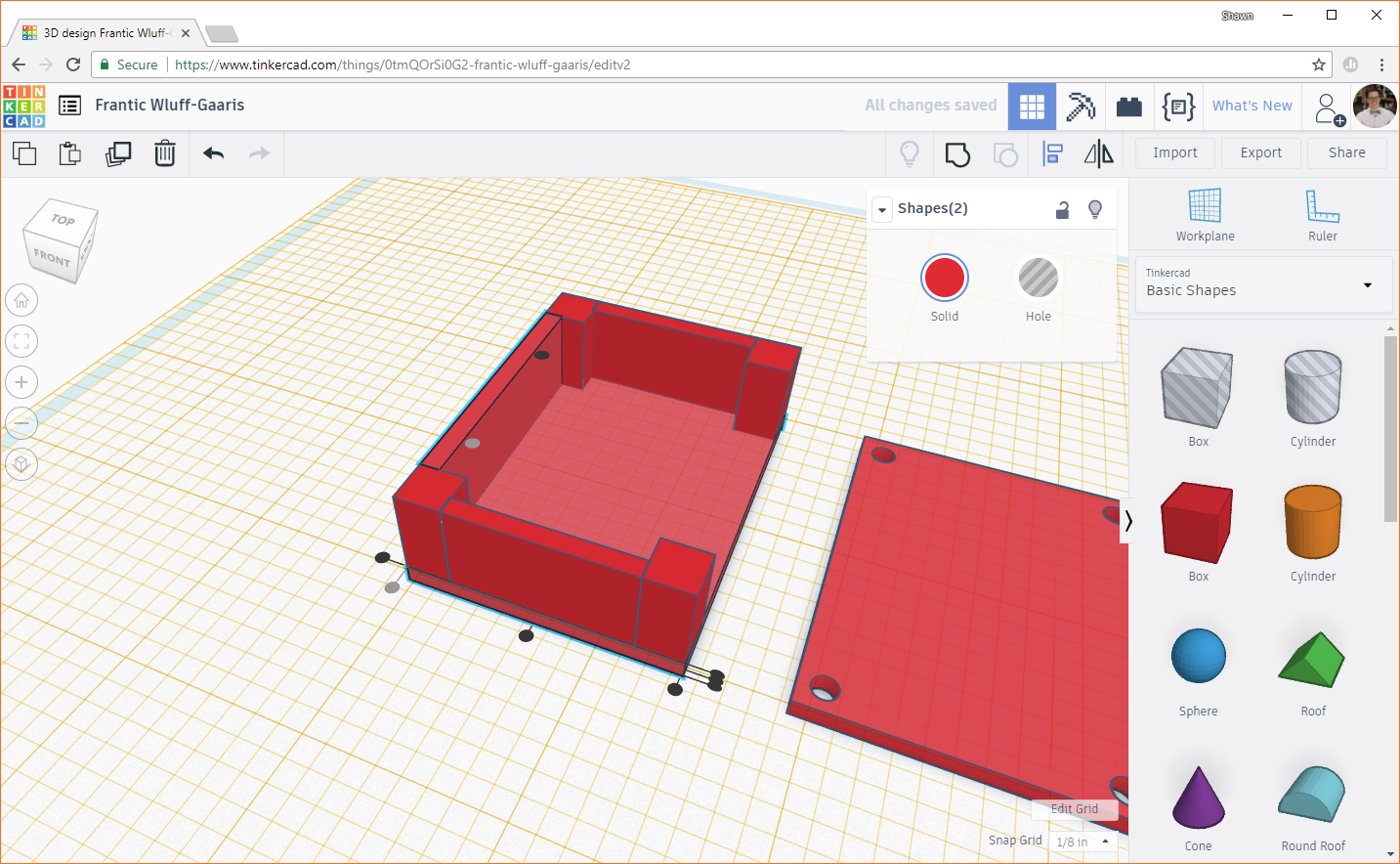
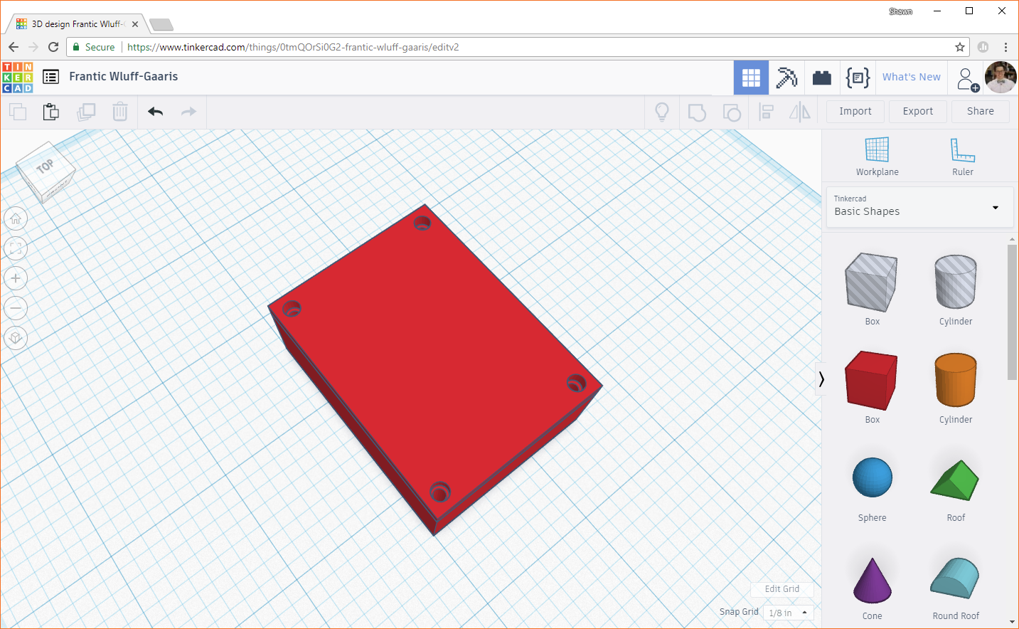
This box will act as the base of our enclosure. We will build the screw posts and walls up around it. However, the lid for our enclosure looks exactly like this base (but with screw holes). To make life easier, let's just copy this base. Click on the box, and then click the Duplicate button on the top left.
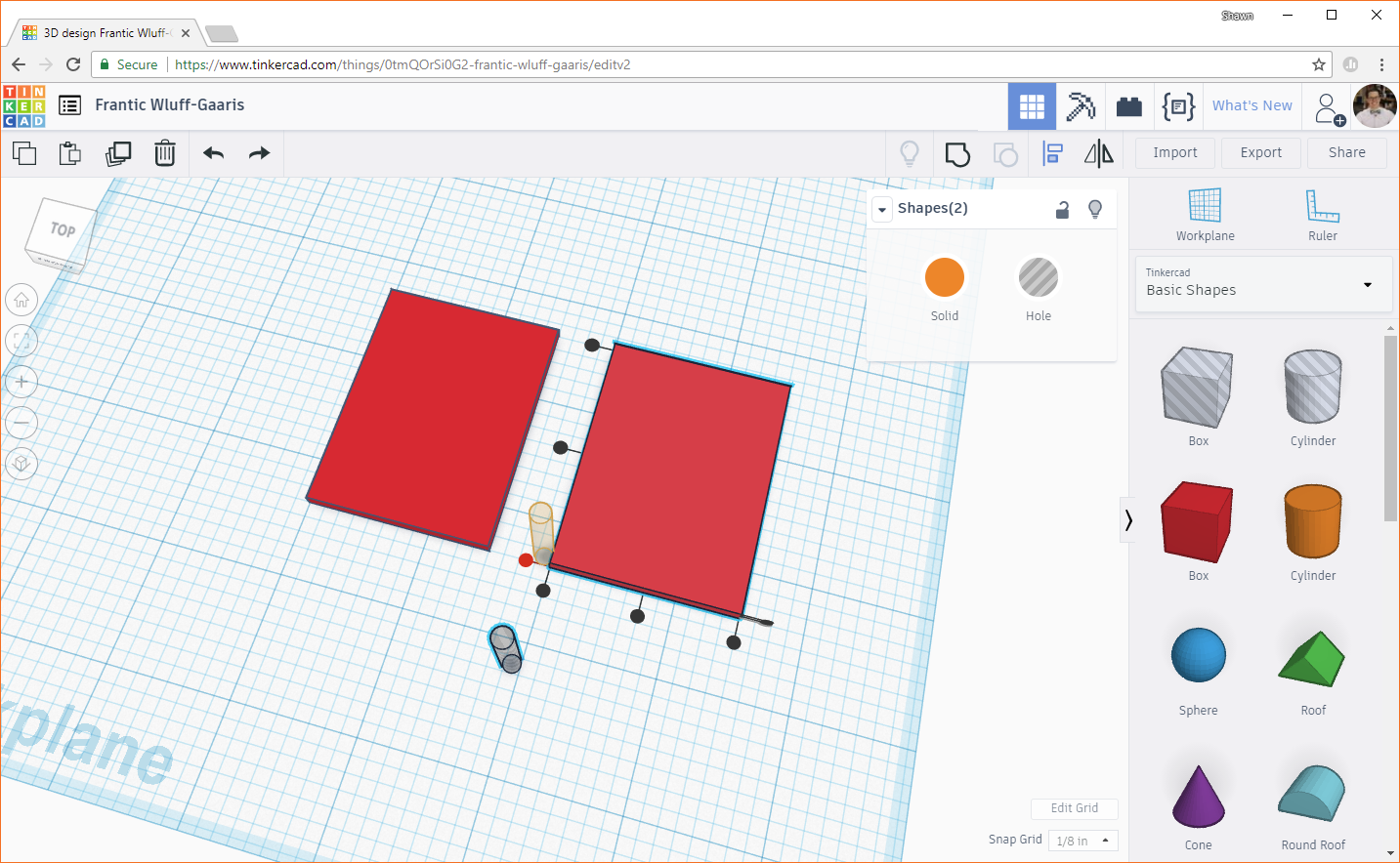
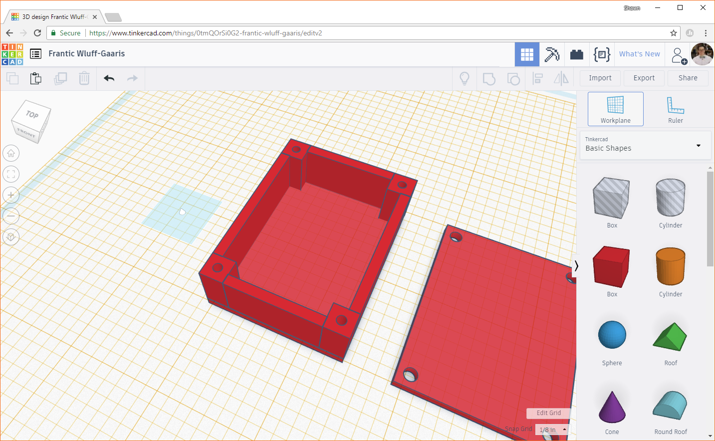
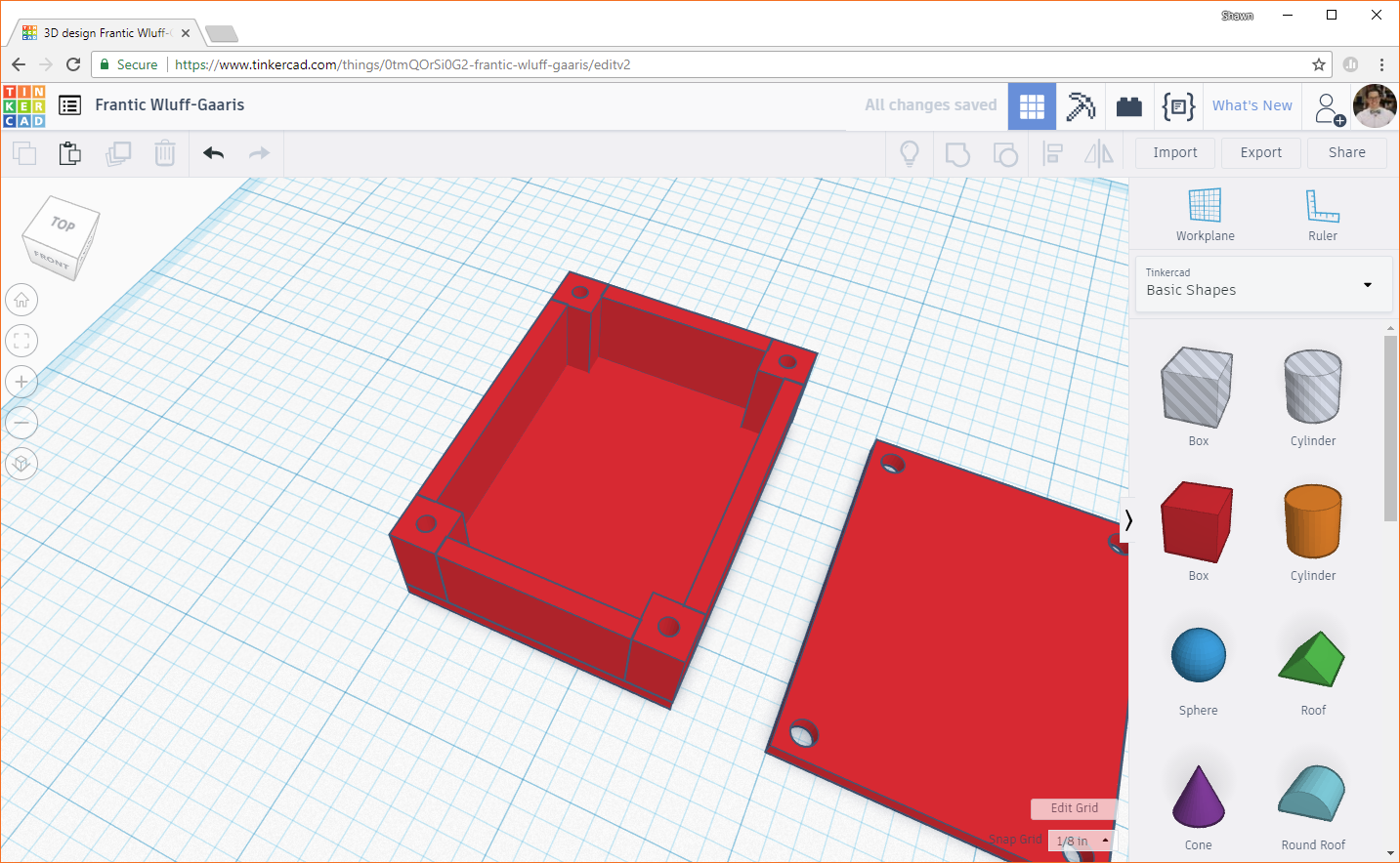
You should now have two of the same boxes taking up the same space. Click on one and drag it over a few inches, making sure to leave a gap between them.
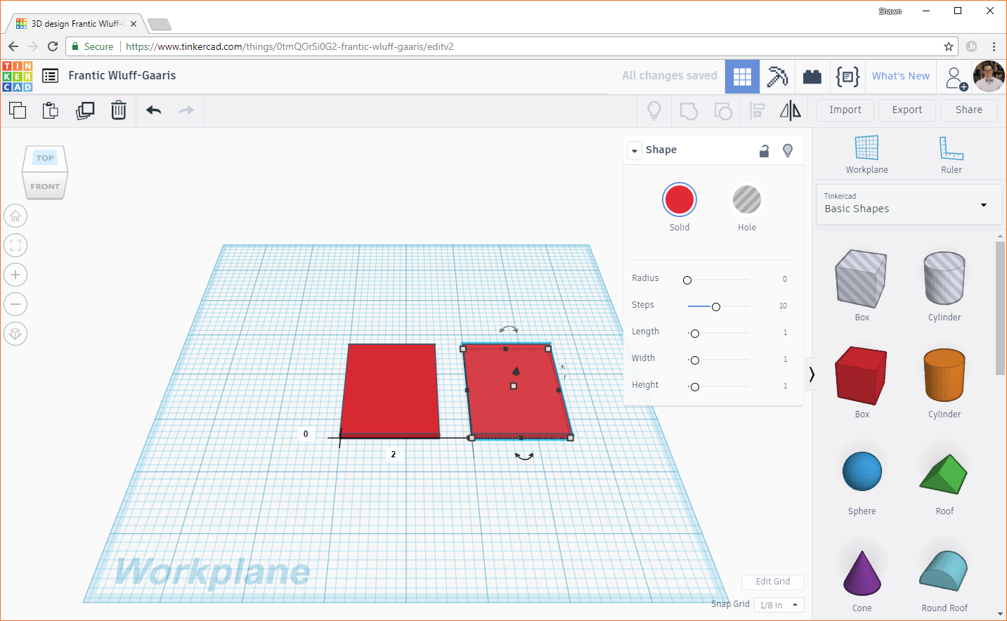
At this point, we should have the foundation for the base of the enclosure as well as the lid.
Drill Holes in the Lid
Let's make screw holes in the lid next. Above the red box and orange cylinder objects on the right pane, you should see a box and cylinder with gray stripes. These are "hole" objects that are useful for cutting, notching, and drilling into other objects. It's helpful to think of them as negative objects that subtract parts from other objects.
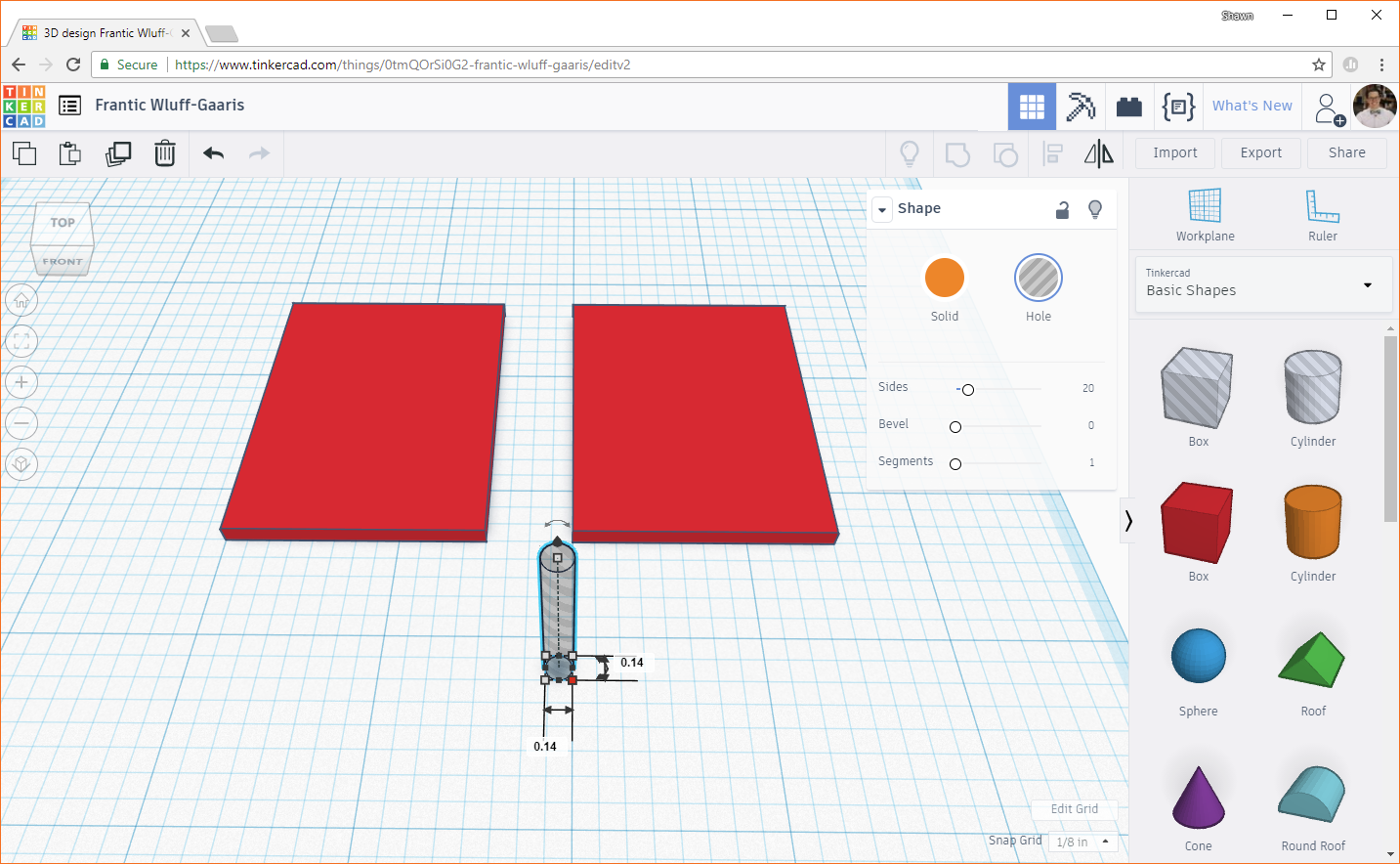
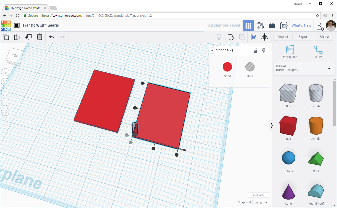
Drag one of the gray striped cylinders to the workplane and change the width and height dimensions to 0.14 inches (remember from the drawing: the screw holes in the lid need to have a diameter of 0.14 inches). The height doesn't matter, as we'll be using these to "drill" into the lid (so long as it's at least as tall as the lid).
Because everything is relative in Tinkercad (there is no 0,0 origin, unless you create an arbitrary one with the ruler--but we won't need to do that for this tutorial), we will need to align the cylinder with the corner of our lid and move it from there to precisely place it. Select both the cylinder and the second box we created (left-click and drag a selection around them, or hold shift and click on both the cylinder and box).
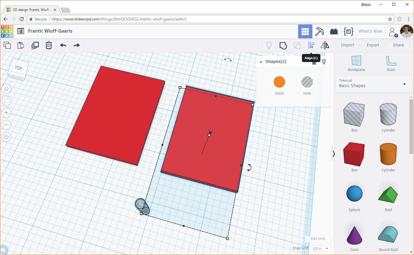
In the upper-right corner, select the Align button. You should see several black dots appear around both of your selected objects. If you hover your mouse over one of these dots, you should see an outline of where the objects will move to should you click it. But don't click!
We don't want both objects to move! We just want the cylinder to move in relation to the box. To accomplish this, click on the box (the one that we have selected). You should see the set of black dots disappear and another set appear around the box. This indicates that the box will stay still and the cylinder will align with the box (instead of both objects moving). Hover your mouse over the bottom black dot on the left side. You should see an outline of where the cylinder will move.
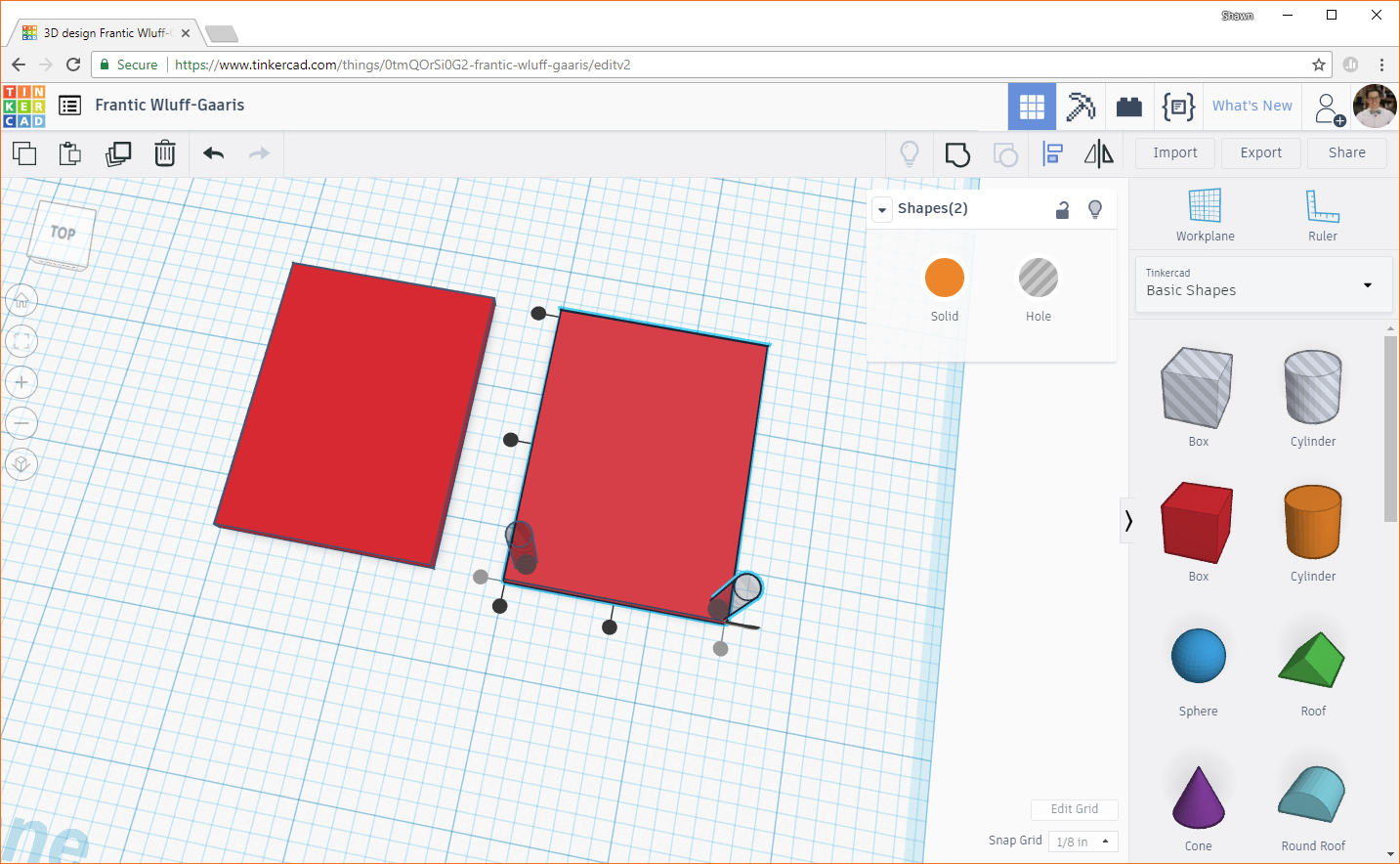
Click the black dot (bottom dot on the left side) to move the cylinder. This aligns the bottom of the cylinder with the bottom of the box.

Click the left-most dot on the bottom side of the box to align the left side of the cylinder with the left side of the box.
If we were to subtract the cylinder from the box to get our hole right now, we'd end up with some edges of the walls with 0 thickness, which doesn't make for a very strong mounting hole. To fix this, we need to move the cylinder in toward the center of the box by a small amount.
We want the screw holes to line up in the center of the posts, which have a footprint of 0.25 x 0.25 inches. This means that the center of each post is 0.125 in from each side of the corner. Right now, the center of the cylinder is 0.07 inches away from each side of the corner. This means that we need to move the post 0.055 inches in from each side in order to line up with the center of the post (0.125 - 0.07 = 0.055). Here is a diagram of how we came to that measurement:

Click on the cylinder and begin to drag it toward the center of the box. You should see a couple of numbers appear showing how much you're moving the object in the X and Y directions (along the plane--note that we can't move objects in the Z direction by dragging them).

Click on one of those numbers to edit it. Pay attention to the sign! If you see a negative sign (for example, in the picture above), you need to keep your number negative. We need to precisely move the hole in 0.055 inches from the sides. From the picture above, change -1/4 to -0.055 and change 0.235 to 0.055.

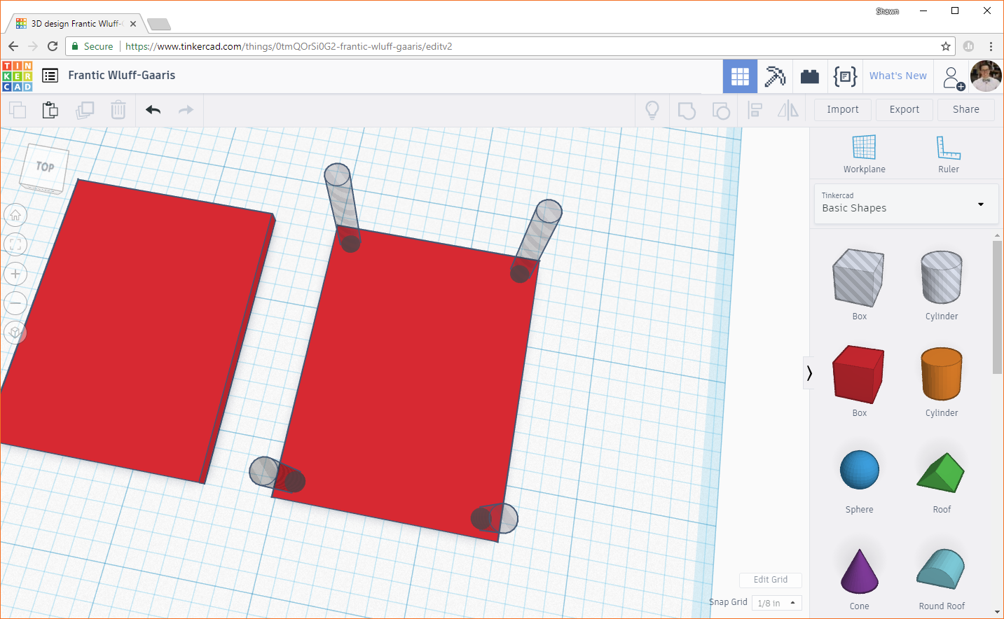
Duplicate the cylinder, and align it to another corner.
Move the cylinder in toward the center, and edit the values so that it moves exactly 0.055 and 0.055 inches (remember to watch your signs!).

Repeat this process for the other two corners. You should have 4 "hole" cylinders in the corners, and each should be 0.055 inches away from their closest walls.
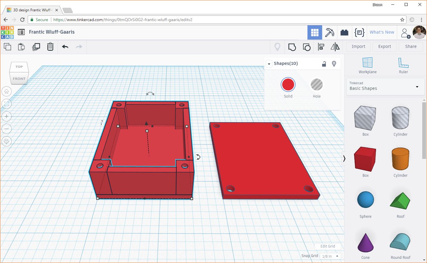
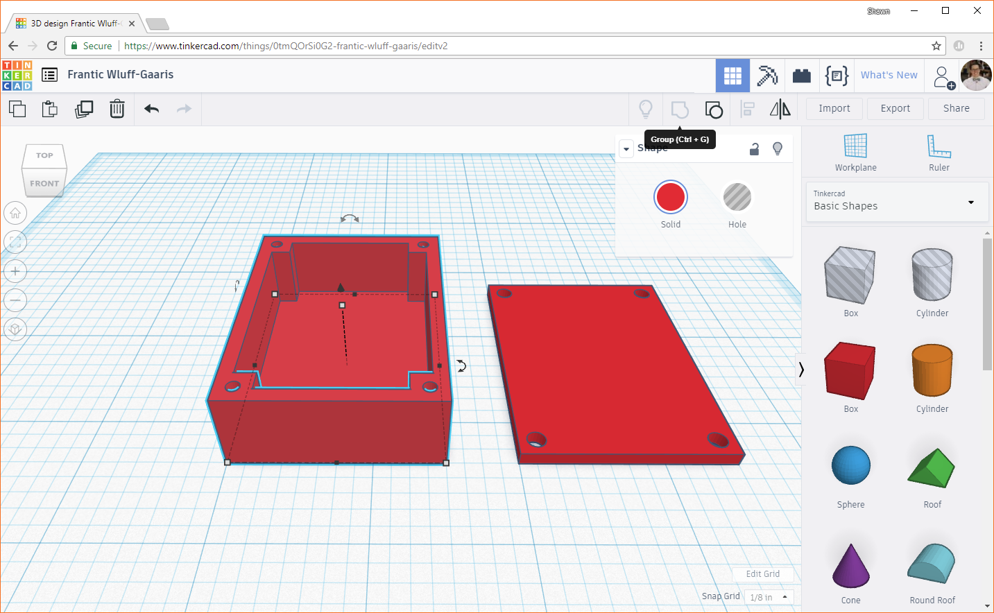
Click and drag a selection box around the lid and four cylinders (or hold shift and select each object). Make sure you do not select the other box!
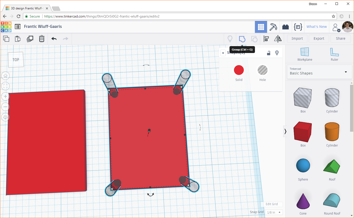
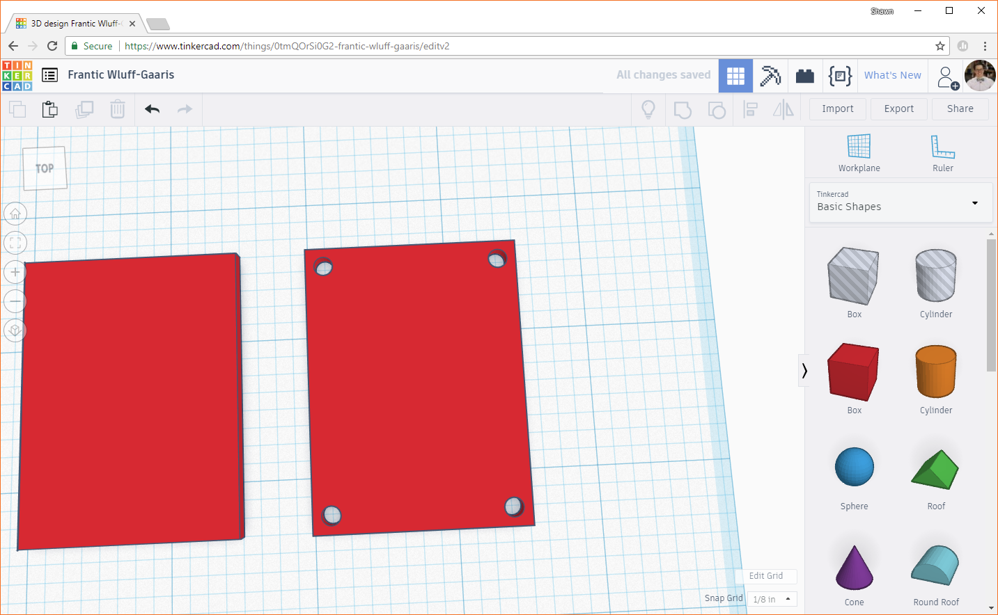
In the top right corner, click the Group button. This will combine any selected objects into one object. Solid shapes (like our boxes) will be added together. Negative shapes (like our "hole" cylinders) will be subtracted from solid shapes. This has the effect of "drilling" or "carving" out shapes. You should see our lid with 4 holes drilled in the corners.
Make the Posts
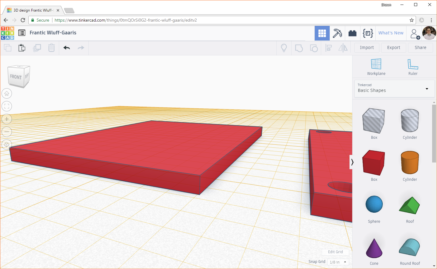
We need to make the posts on the main enclosure body next, but first, we need to move the workplane. The workplane is the 2-dimensional area that provides an area for objects to be created on, and we can move it to be parallel with any surface of an object we've already created. By moving it up to be in line with the top of the enclosure's foundation, we can make the posts directly on the top of the foundation. That way, we don't have to move the posts up (in the Z direction) later.
Click on the Workplane button in the top right of the window. You should see a square with a cone sticking out of it appear on your cursor. Hover over the top of the foundation. The square shows the orientation of the plane (parallel to the top of the foundation), and the cone shows the direction of positive Z (positive Z will be up away from the top of the foundation).

Click, and you should see the workplane move to the top of the foundation and turn yellow (to show that it is a user-defined workplane as opposed to the blue default workplane).
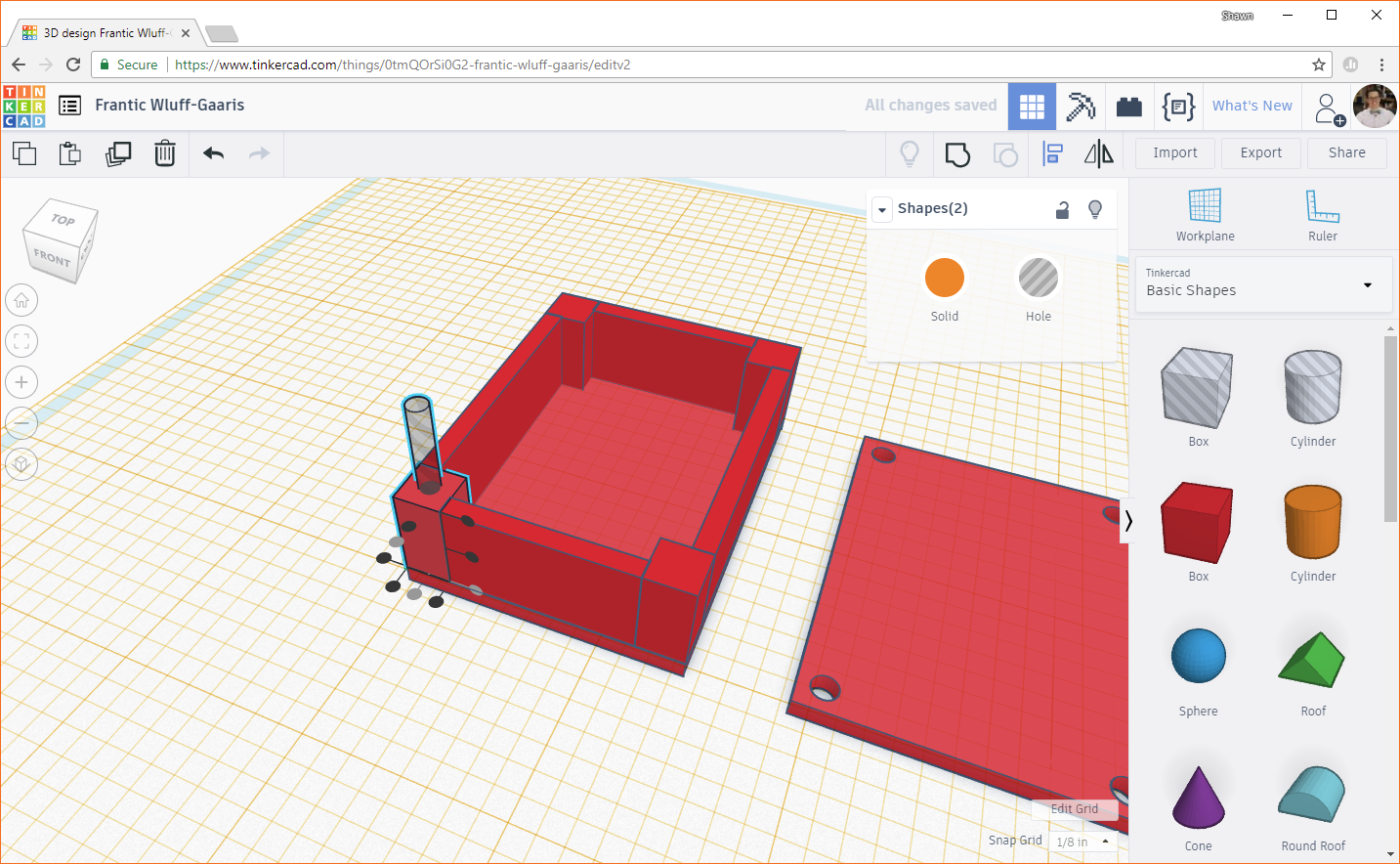
Add another solid box to the workplane. Change the footprint (X and Y) dimensions to 0.25 inches each.
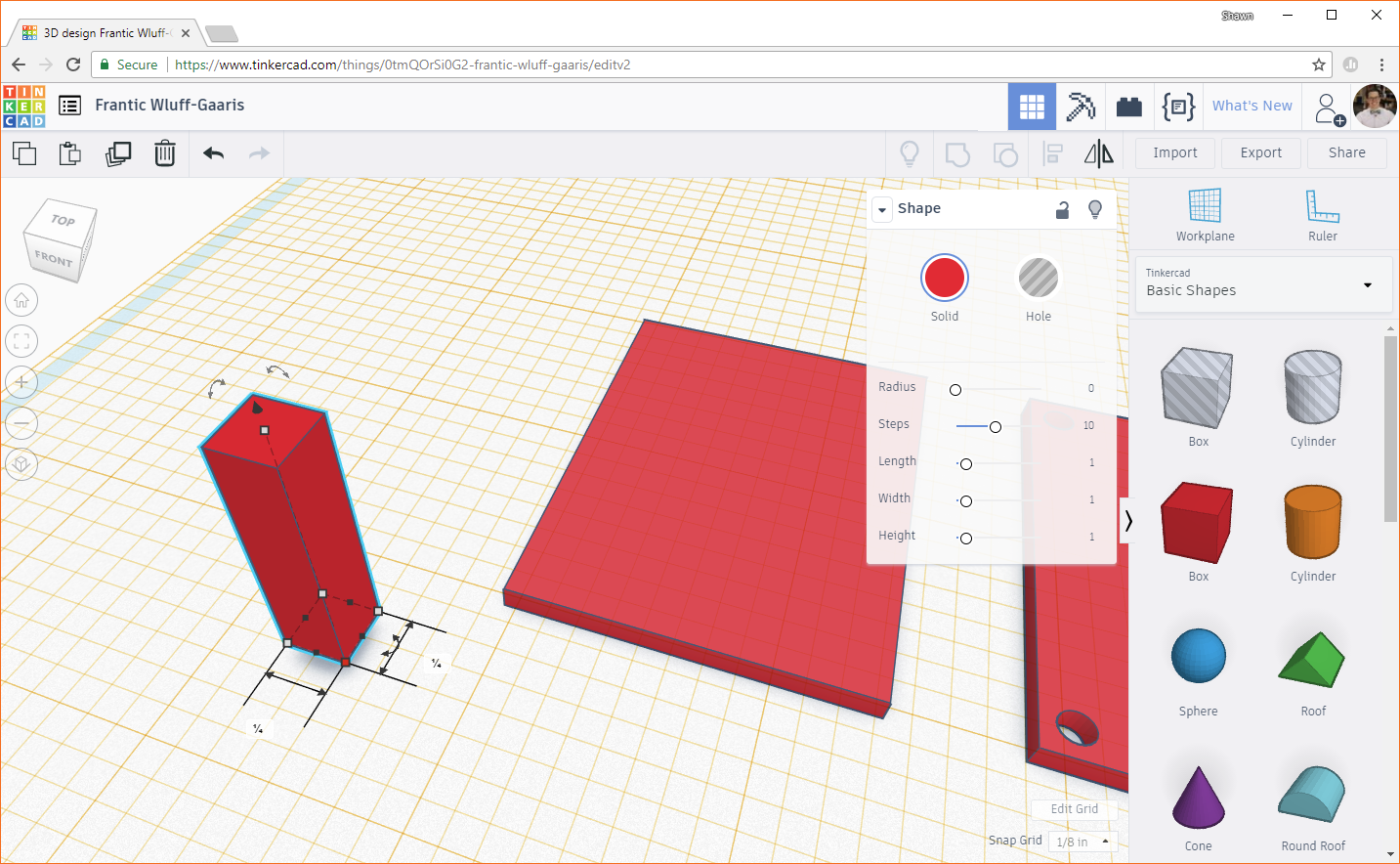
Change the height to 0.5 inches. The height of the posts determine the amount of space in the Z direction in the enclosure.
Use the Align tool to line up the corner of the post with a corner of the foundation.
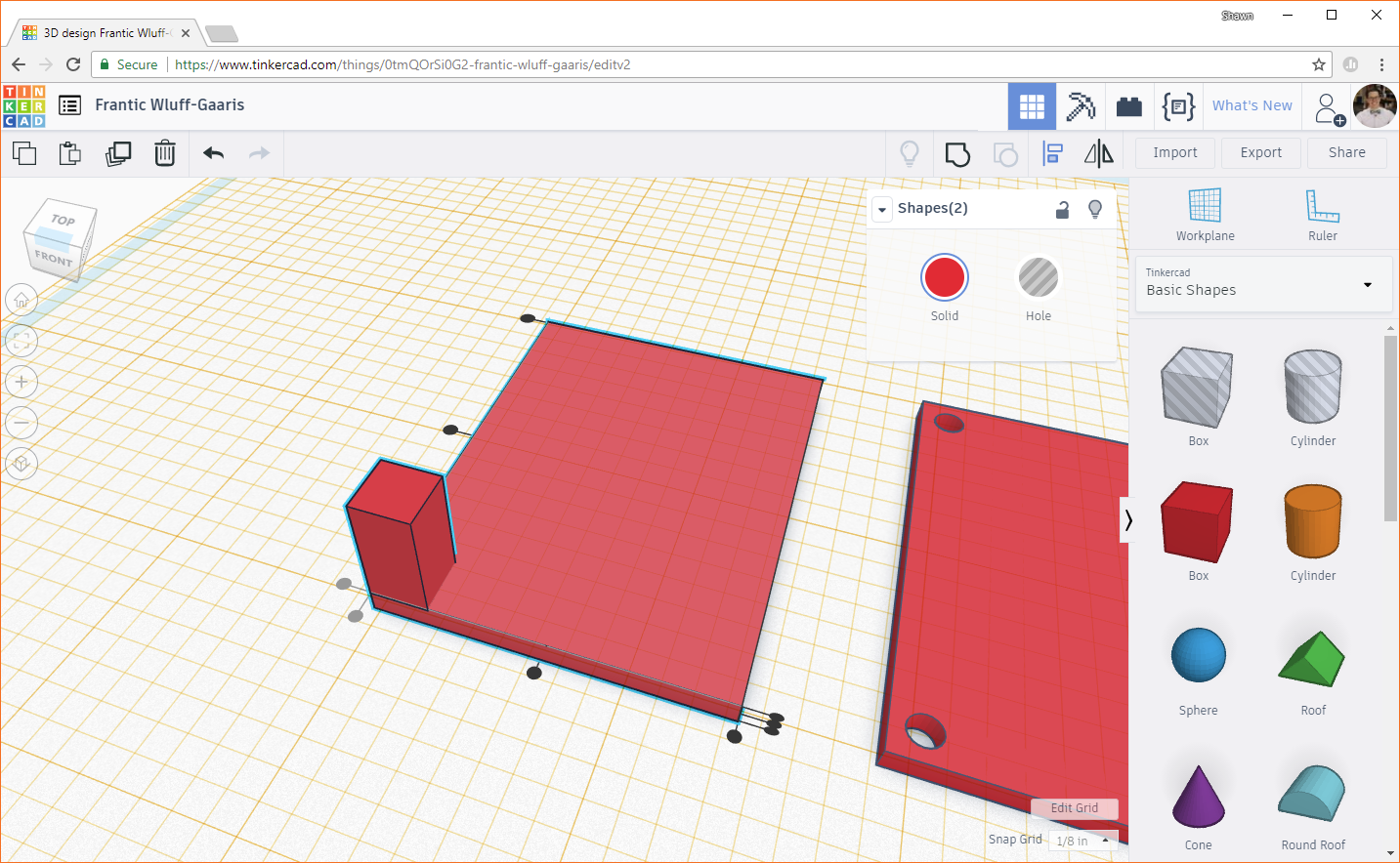
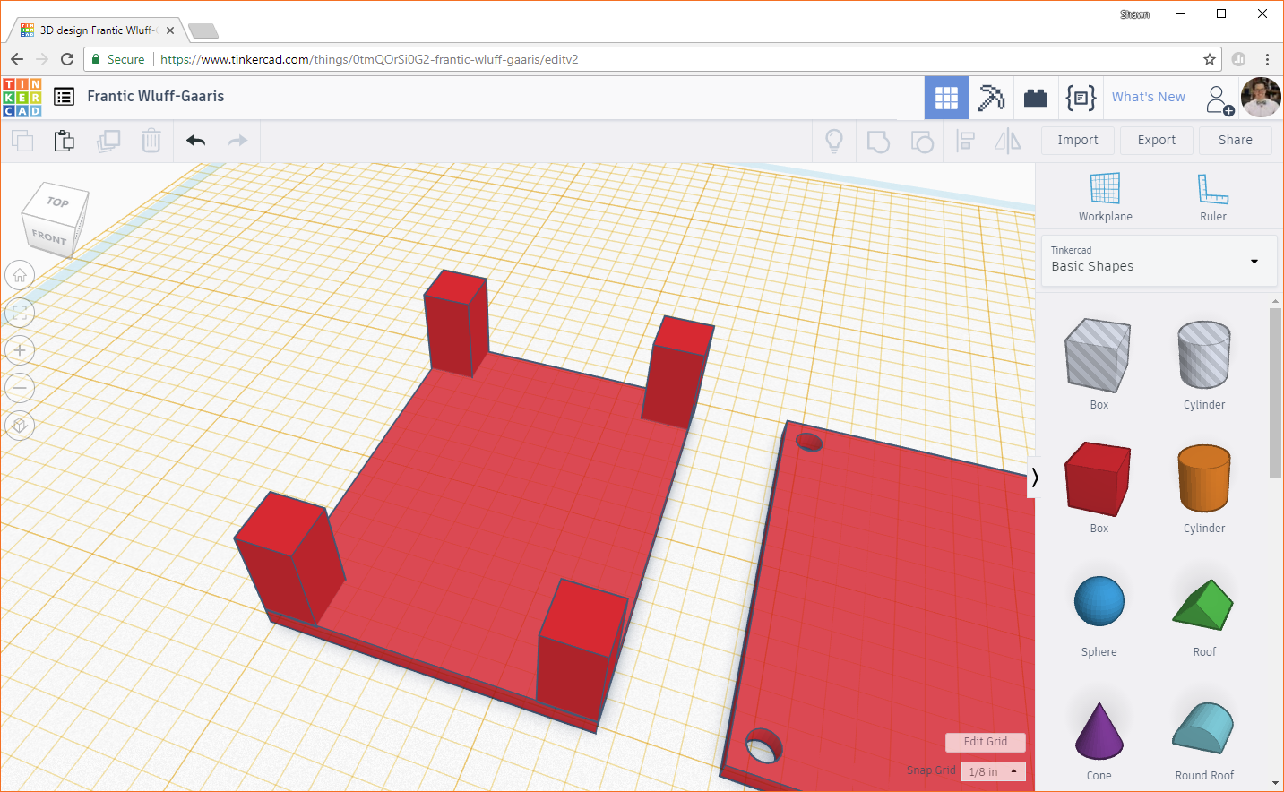
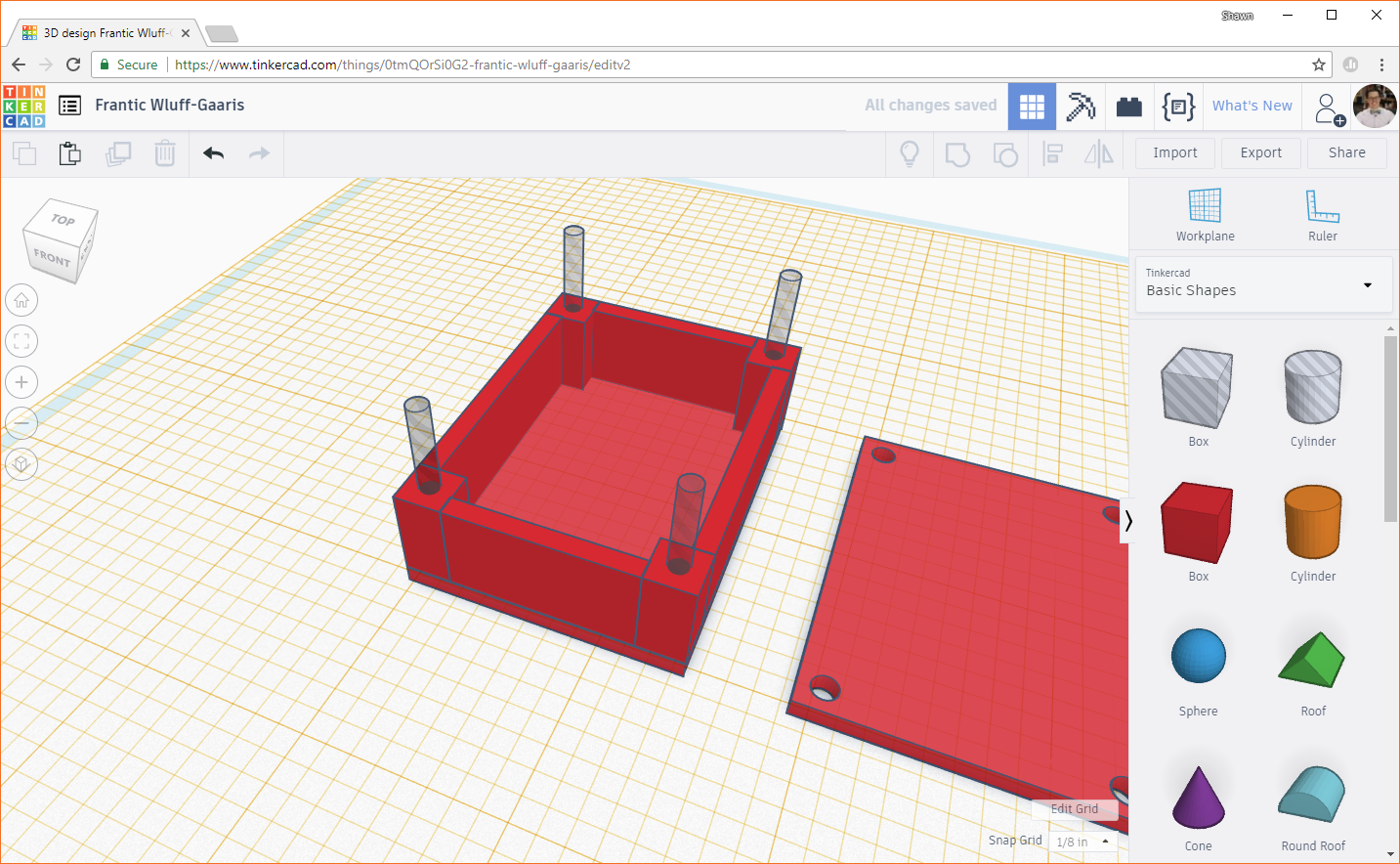
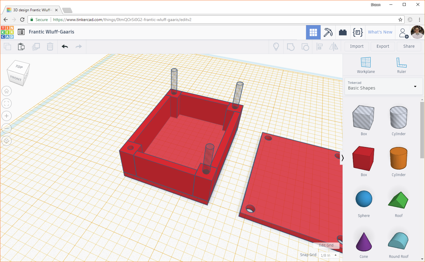
Duplicate the box 3 times and align each of them in a different corner of the foundation.
Build the Walls
At this point, we'll want to add walls to the sides of the box, connecting our posts. Drag a box object to the workplane, and change the X and Y dimensions to 1.0 inches and 0.1 inches. Remember, the width of the box is 1.5 inches. Subtract the width of 2 posts (2 x 0.25 inches), and we get 1.5 - (2 x 0.25) = 1.0 inches. 0.1 inches is the thickness of the wall, which is the same as the box foundation and lid.
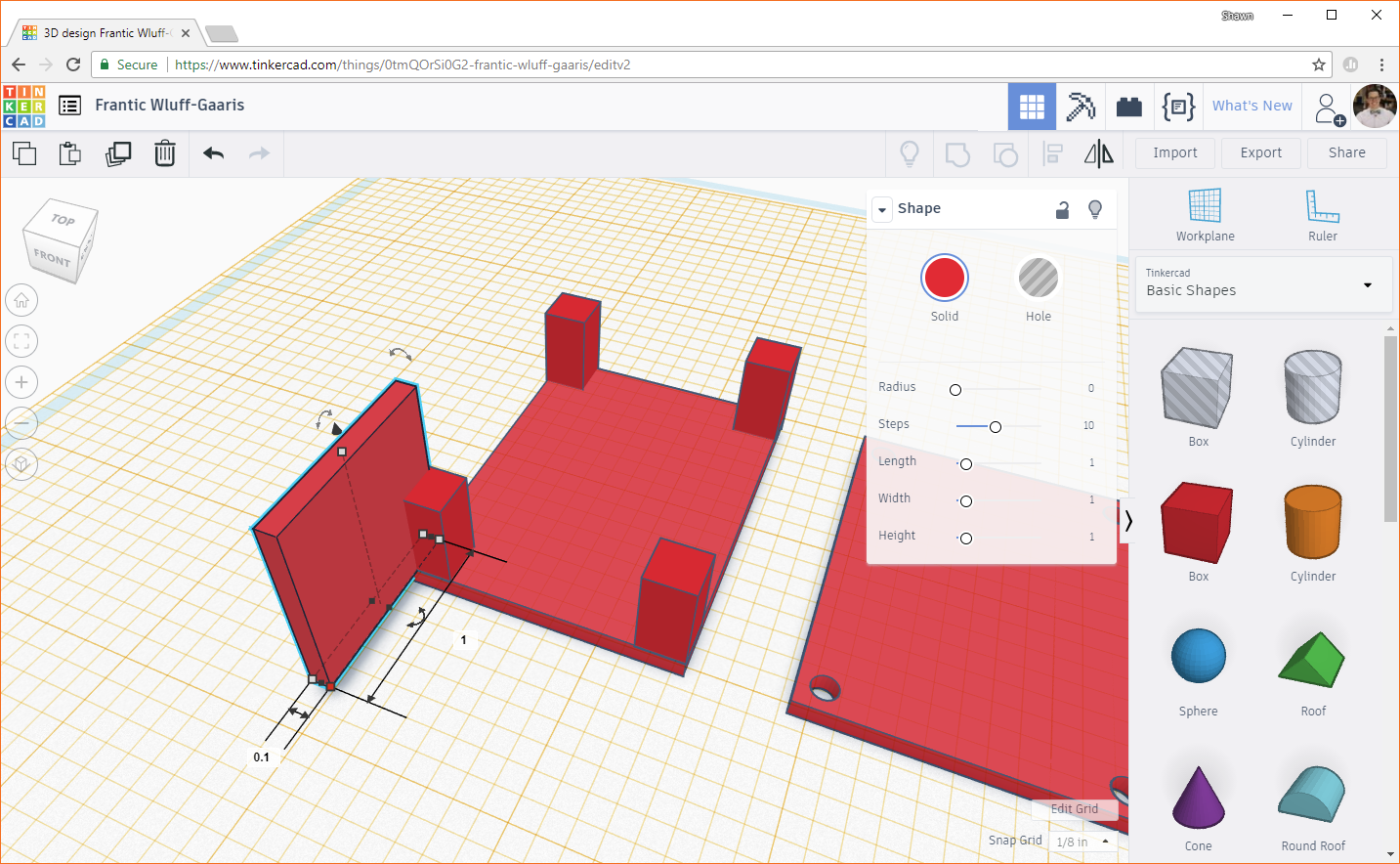
Change the height of the wall to 0.5 inches (which is the same height as the posts).

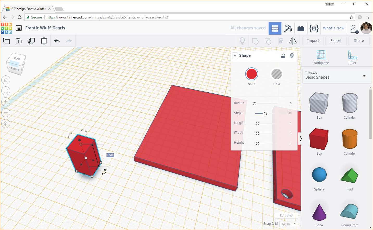
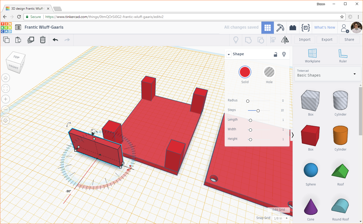
We want this wall to span between posts on the shorter side of the box. If you need to rotate the wall, drag and move the double-sided, curved arrow that's flush with the workplane. Rotate the wall 90 degrees or -90 degrees so that it is parallel with the short side of the box.
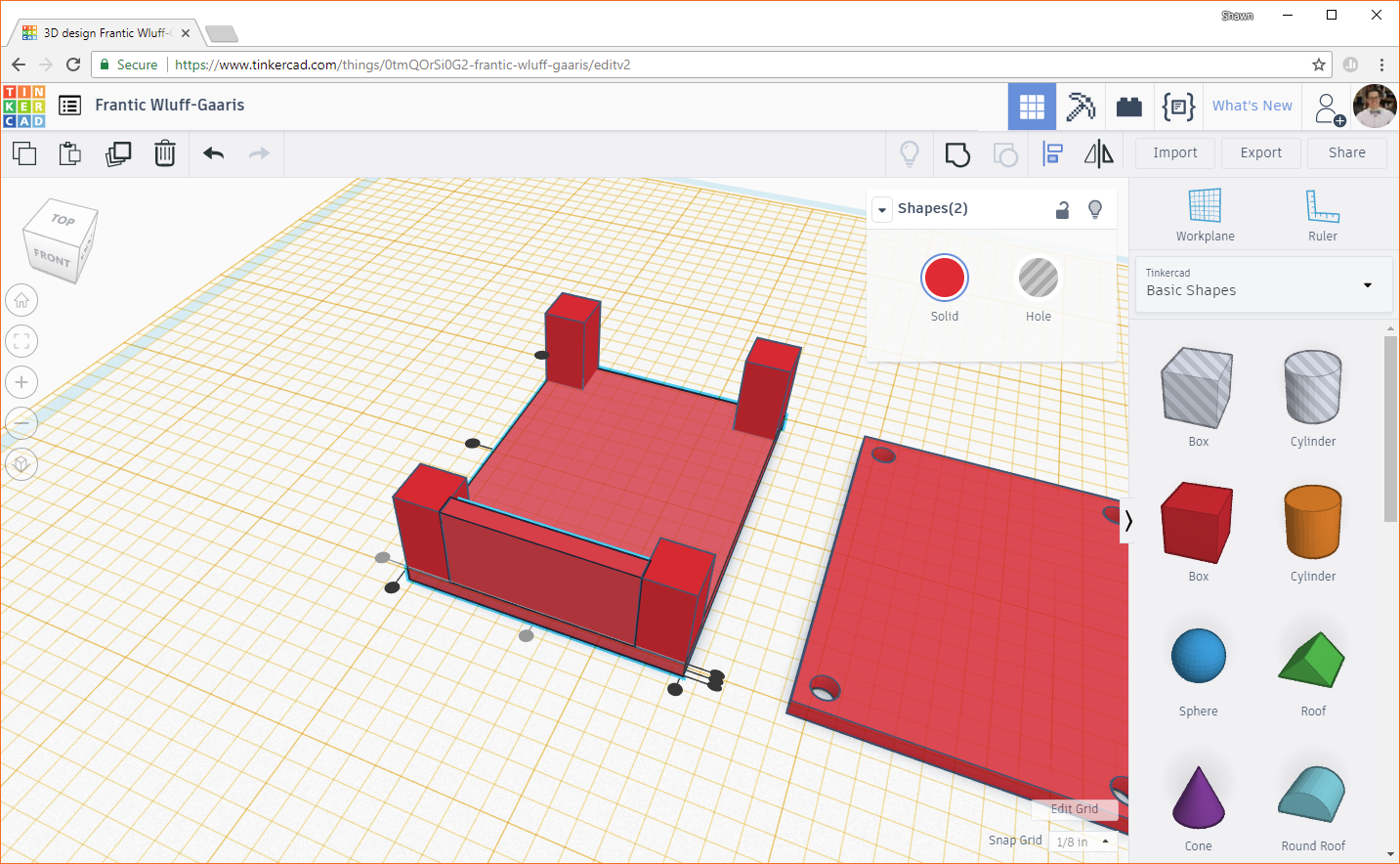
Highlight the wall and the foundation. Click the Align button. Click on the foundation to make the aligning dots appear around it. Click the dot in the middle of the short side to center the wall with the foundation.

Click the dot on the bottom of the left side to position the wall between the posts.
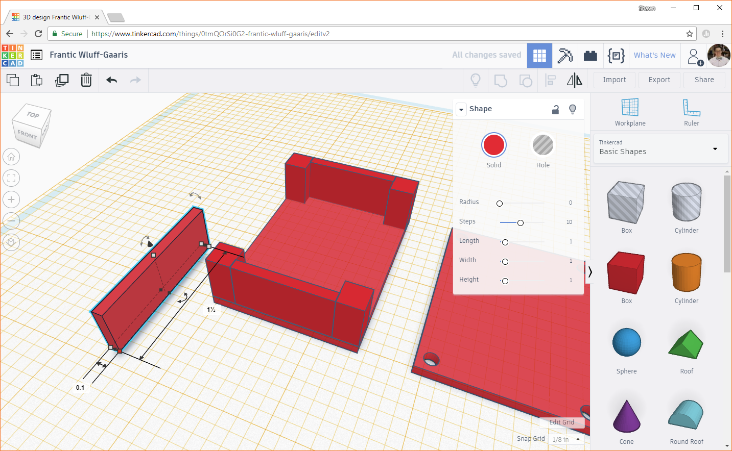
Duplicate the newly created wall and use the align tool to line it up on the opposite side.

Drag in a new box object, and change the X and Y dimensions to 0.1 inches and 1.5 inches. The length of the box is 2.0 inches, so 2.0 - (2 x 0.25) = 1.5 inches. Change the height to 0.5 inches.
Rotate the wall as necessary, and align it between two posts, constructing the wall along the length of the box.
Duplicate the wall, and move the copy to the other side of the box.

Drill Some Holes
Drag a cylinder hole object to the workplane. Change the width and length both to 0.1 inches.

Use the Align tool to center the cylinder in the middle of one of the posts.
Copy the cylinder 3 times, and line them up in the middle of each post.
Select one post and its associated cylinder. Click the Group button to drill out the cylinder from the post.
Repeat this process for the other 3 posts and cylinders.

If you move the camera around, you should see that the holes are drilled into the posts but do not punch through the base. That's because we set the workplane at the top of the base, and any shapes we created stop at the workplane!
Finishing Touches
You could probably print these shapes as-is, but it's always helpful to do a little clean up and verify that everything lines up.
If you need to move the workplane back to its starting position, you can click on the Workplane button in the top right, and hover your mouse over the yellow workplane. You should see the plane cursor (square and cone) turn blue and white.
Click to reset the workplane back to its default position, where it should turn blue.
Right now, the box (minus the lid) is a collection of objects. Some printers may print it as one part, and some may not. It can help to group these objects to tell our slicer program that we want it to be one solid object. Select all the objects in the bottom part of the box (i.e. everything but the lid).
Click the Group button, and all the objects should combine into one.
If you'd like to check that all the screw holes line up, you can move the lid to the top of the box, and look down the holes. Use the Align tool to move the lid precisely to the top. You might need to move the lid up slightly on the z-axis so that it's not inside the box.
Move the camera around to each of the holes to make sure everything is lined up. Once you've verified that the holes look good, press the Undo button (you can also use the keyboard shorcuts ctrl + z or command + z) a couple of times to reverse the changes.
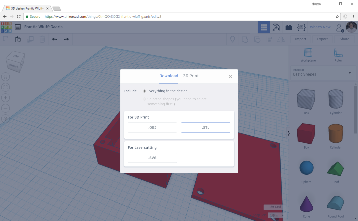
For many printers, we can't print directly from Tinkercad (especially for LulzBot). We need to export our design as a .stl or .obj file and then import it into a slicer program. In the top-right of Tinkercad, press the Export button. You should be greeted with a pop-up. The .obj file format is a more complex collection of files, and the .stl format is easier to work with. With our simple print, we'll go with .stl, so click on the .STL button to download your exported design.