Fingerprint Scanner Hookup Guide
This Tutorial is Retired!
Note: This tutorial is for the GT-511CXX models. If you are using any of the newer models (i.e. GT-521F32 and GT-521F52), please refer to the new Fingerprint Scanner (GT-521Fxx) Hookup Guide.
View the updated tutorial: Fingerprint Scanner (GT-521Fxx) Hookup Guide
 bboyho
Troubleshooting
Listed below are frequently asked questions and tech support tips on troubleshooting common issues related to the fingerprint scanner.
1.) The fingerprint's green LED indicates that it is powered and the connection is correct. However, the fingerprint scanner is not responding to any of the commands with my Arduino. What can I do?
Make sure that there are no loose connections. If you are using the JST SH jumper 4 wire assembly, the cable's wire is relatively thin compared to the Arduino's socket. A small bump can break the connection requiring you to power cycle the fingerprint scanner or reset the Arduino.
Also, make sure that you are connecting the fingerprint scanner to your microcontroller correctly based on the Arduino model and defined software serial pins.
2.) Scanner not recognizing your fingers when enrolling?
There can be issues trying to enroll when using the SDK_Demo.exe or Arduino example code. This is usually due to fingers being dry and not having good contact on the scanner. The finger has to have the same pressure applied and be placed in the same position for all three enrollments. The timing of your finger on the scanner is a little tricky too. A tech support representative had to try a few times before it was able to enroll a finger. This is common with any fingerprint scanner like the one that is on a smartphone.
If you see these errors, you probably did not place your finger on the fingerprint scanner sufficiently for each enrollment:
Bad finger!
or
Failed to capture second finger
or
The enrollment is failed!
If you are using an FTDI, try to follow the directions for enrolling with a FTDI again. You may need to close out the program and unplugging/replugging the FTDI before re-enrolling. If you are using an Arduino, try the enrollment process again by placing your finger on the scanner, resetting the Arduino, and following the directions in the serial monitor.
3.) Scanner not recognizing your fingers when verifying?
If you are trying to verify a fingerprint, make sure to place the finger on the scanner just like when it was enrolled. The same conditions for scanning a fingerprint apply as explained above for enrolling.
4.) My fingerprint scanner is getting warm to the touch.
This is normal. The fingerprint scanner can get warm to the touch if you are using the Arduino example code and constantly scanning. When completing your project, try turning off the fingerprint scanner's blue LED or write a condition statement to identify a fingerprint only after pressing a button. You can also try to use an input voltage of 3.3V. However, you need to make sure that it is getting sufficient current. You can also try adding a condition statement to identify a finger when a button is pressed. There is a note in the datasheet on page 4 where
"... The sensor's metal frame can be integrated with a touch IC to wake up the module."
5.) Will the GT-511C1R fingerprint scanner work with the FPS_GT511C3 library?
Yes, it will. It has been tested. Each of the fingerprint scanners use the same command protocols so the Arduino example code can be used for any of the scanners. However, the library will not be compatible if you using a different scanner that is not manufactured by ADH-Tech.
6.) Can I use an Arduino Due?
Unfortunately, the fingerprint scanner's Arduino example code for the does not work with the Arduino Due. You would need to modify the code and use it with the hardware serial UARTs because the Arduino Due does not support software serial. This old forum post will explain why there are compilation errors with the example code using the Arduino Due board definition => Arduino.cc Forums: SoftwareSerial for Arduino Due.
7.) What are the dimensions of the fingerprint scanner?
The dimensions do not seem to be listed in the datasheet for the GT-511C3. The size should be the same as the GT-511R model on pg 37 of the datasheet.
8.) Is there a 3D Model?
Yes, there is a 3D model of the fingerprint scanner in SparkFun's GitHub repository located here.
9.) I soldered to the back of the fingerprint scanner and none of the Arduino examples work.
Those pins are broken out if you wanted to connect the fingerprint scanner directly to a USB port. The USB data lines are different from a serial UART protocol. If you are using the Arduino examples for your project, it is recommended to connect to the JST SH connector. If you are interested in plugging the scanner directly to your computer's COM port, feel free to test it out and experiment. It has been tested to work with the GT-511C1 (retired), GT511C3, and GT-511C1R models.
Fingerprint Scanner USB Pinout
Surprise! You found the extra section on how to connect to the USB pins! The connection to the USB was not included in the beginning of the tutorial because the main objective was to use it in an embedded project with an Arduino microcontroller. To connect the fingerprint scanner with the demo software and your computer's USB port, you can connect the pads on the back of the board labeled J1 directly to the USB port of your computer. The image below shows the pinout:

Using a multimeter and testing it out, I was able to determine the pinouts. Here are the connections that you would need to make:
| Fingerprint Scanner | USB Port |
|---|---|
| Shield (left most pin) | USB Shield (not necessary if using a USB breakout board). Tied to GND. |
| GND | GND (Standard USB Black Wire) |
| D+ | D+ (Standard USB White Wire) |
| D- | D- (Standard USB Green Wire) |
| Vcc (square pad) | 5V (Standard USB Red Wire) |
Below are the parts and tools that you would need to make a USB connection:
- Micro-B USB Breakout Board
- Right Angle Breakaway Male Header Pins
- USB Micro-B to A Cable
- F/F Pack of 10 Premium Jumper Wire or [ Hook-Up Wire - Assortment and Female Header ]
- Wire Strippers - 30AWG (Hakko)
After gathering the parts, you will need to prepare your fingerprint scanner for soldering and decide how you want to connect to the fingerprint scanner. For this example, I decided to use the female header pins to easily connect/disconnect from the USB breakout board.
a. Cut 4x wires using the wire stripper. b. Wire strip the wire's end. c. Solder the exposed wires to each of the respective pads on the fingerprint scanner. d. Break off a 1x4 row from the right angle breakaway header. e. Solder the header pins to the plated through holes of the micro-B USB breakout board. f. Clean solder joints on the fingerprint scanner and the breakout board. Be careful not to get any water inside the fingerprint scanner's enclosure. It can be damaged if there is any water in the enclosure after powering up. g. Dry the boards.
The image below shows how solder joints should look like with the fingerprint scanner on the center and right.

Below is the expanded view of the fingerprint scanners. As you can see, you are not limited to only using F/F premium jumper wires. You could use a row of female header pins, heat shrink, and wire.

The Art of Braiding Wires
The next step is not necessary. However, if you are looking to manage your four wires, try braiding them. I was inspired by McCall's tutorial when completing projects. To braid your wires, twist the black and blue wires in a clockwise pattern between your index finger and thumb of both hands.

Repeat for the green and red wires.

Twist the black/blue pair with the green/red pair in the opposite direction (counter-clockwise).

Connecting to a USB Port
After soldering, you will be able to connect the wires to your micro-B USB breakout. Align the connection between the headers and your micro-B USB breakout board as shown in the image below:

Finally, connect the USB cable between your computer's COM port and the micro-B connector. The device will show up as a USB Mass Storage Device on My Computer . For the retired GT-511C1, it will show up as "Gingy Disk (G:)" and under device properties, it might say "Finger Mass Storage1 USB Device". The GT-511C3 will show up as "CD Drive (G:)" and under device properties, it may say "Holtek Mass Storage1 USB Device". The GT-511C1R will also show up as "CD Drive (G:)" and the device properties might say that it is a "Fingerprint USB Device".
Note: Certain USB Cables maybe have D- as green and D+ as white. If the fingerprint scanner is not recognized by your computer in the device manager or there is a warning message, try reversing the data pins and it should enumerate properly.
Demo Software Development Kit (SDK) w/ USB
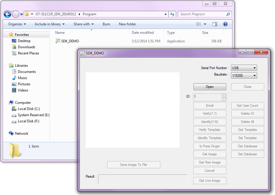
Once connected to your computer's USB port, you will be able to use the demo SDK software just like the FTDI and Arduino w/ a Serial Passthrough examples explained in the tutorial. For the Serial Port Number , leave it at USB. The Baudrate: can be left at 115200. Just make sure that you are using the SDK demo software that was linked on the model's product page. Using the GT-511C1R with the GT-511C3's SDK will not work. The image below shows the GT-511C1R with the its SDK demo before clicking on the "Open" button:

You will not have access all the functions provided in the SDK_Demo.exe. One interesting feature of using the USB pins directly is that an image will also scan as you are using the scanner to identify the fingerprint.