Fingerprint Scanner Hookup Guide
This Tutorial is Retired!
Note: This tutorial is for the GT-511CXX models. If you are using any of the newer models (i.e. GT-521F32 and GT-521F52), please refer to the new Fingerprint Scanner (GT-521Fxx) Hookup Guide.
View the updated tutorial: Fingerprint Scanner (GT-521Fxx) Hookup Guide
 bboyho
Hardware Hookup
The fingerprint scanner requires a serial UART connection and power. There are a few options to connect to the sensor depending on what UART device you are using. The easiest would be to use an FTDI but you can also use any microcontroller that has a UART.
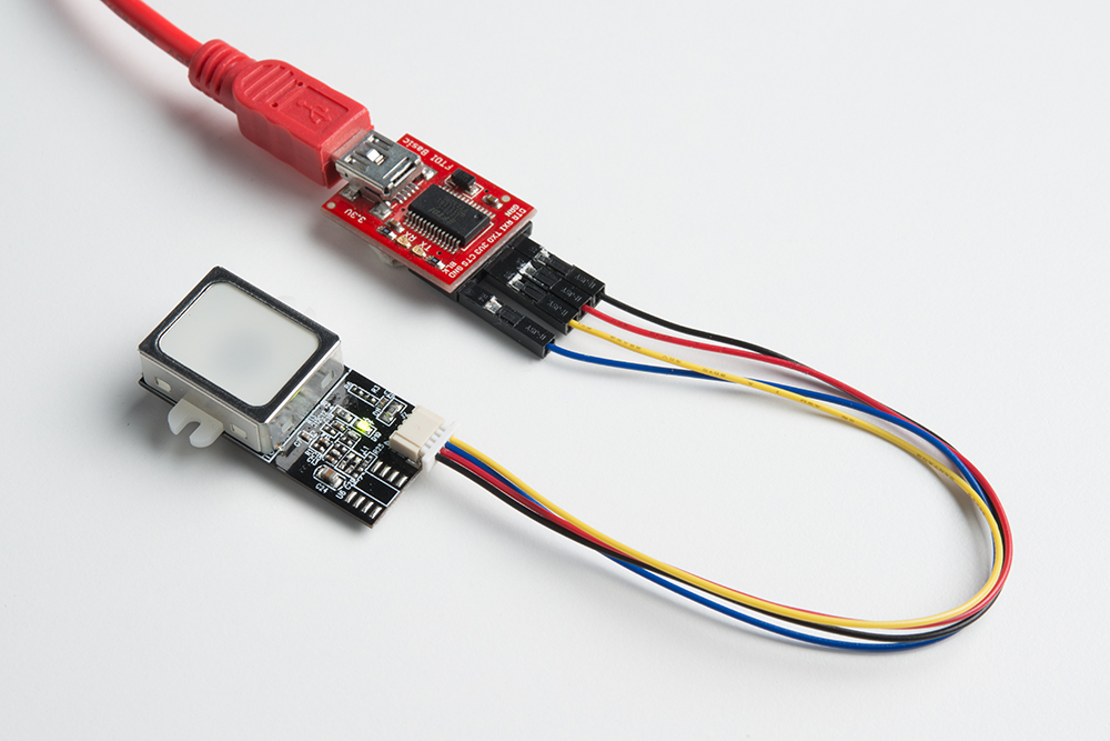
1.) Connecting w/ a 3.3V FTDI
Option 1: Qwiic Cable
To connect the fingerprint scanner to your computer, it is recommended to connect the JST SH cable to a USB-to-serial converter. Here are the minimum required parts you would need to get started:
- Fingerprint Scanner (GT-511C3 or GT-511C1R)
- Qwiic Cable - Breadboard Compatible
- 3.3V FTDI Basic Breakout
- Mini-B USB Cable
Below are the following connections you would need to make with the JST-SH connector labeled as J2:
| Fingerprint Scanner [Pin #] | FTDI 3.3V |
|---|---|
| UART_TX (3.3V TTL) [Pin 1] | RX |
| UART_RX (3.3V TTL) [Pin 2] | TX |
| GND [Pin 3] | GND |
| Vin (3.3V~6V) [Pin 4] | 3.3V |
After connecting, the green LED will power up like the image below.
Option 2: Making a Custom Adapter
If you are using the JST SH Jumper 4 Wire Assembly instead of the Qwiic cable, it is highly recommended that you make a custom adapter by soldering to the ends of the wire for a secure connection. This will ensure that the connection is not loose when inserting it into female header sockets of an FTDI or the RedBoard/Arduino Uno. The cable wire is small compared to the female header socket. A small bump can mess with the serial UART or power between the fingerprint scanner and converter. This may require you to reconnect the scanner to your computer or device. Making an adapter will also provide quick access to the small 4-pin JST-SH connector that is on the scanner. Here are the minimum parts to make a secure connection:
When soldering wires to a header pin, the tools listed below can help make your life easier but are not required:
- SparkFun Third Hand Kit
- Hot Air Rework Station or Heaterizer
- Piece of Medium Density Fiberboard (MDF) or Heat Resistant Board
- Tape
One method of making your custom adapter is to solder the wires to a row of header pins. To do this, you will need to:
- Break off a row of 1x6 straight header pins.
- Cut 4x pieces of heat shrink for each wire, and thread the wires through the heat shrink.
- You will need to hold the long end of the header pins in place while soldering the wire to the short side. A third hand was used to clamp down the pins. You can also tape them down.
- The JST-SH cable's wires should already be stripped. To prevent damage to the surface that you are working on, you could use MDF or any heat resistant material. Align the wires to the short side of the male header pins and use some tape to hold the wires down. You would be wiring the black wire to pin 1 (next to the notch indicating the polarity on the connector) to the Rx pin of your FTDI. Make sure that the conductive wire is exposed for soldering.
- Using a soldering iron, solder the wires to the header pin. Be careful not to leave the soldering iron on the wire and header pin for too long. The wire's insulation will melt off and the metal pin can begin to move around the black plastic housing due to excess heat. Try just brushing the solder with the soldering iron across the wire and pin. If using lead-free solder, flux is highly recommended.
- To reinforce and secure the connection between the wire and header pin, slide the heat shrink over the solder joint.
- Using hot air from a rework station, heat the strip until it shrinks and wraps around the solder joint.
- (Optional) Remove any flux residue left on the connection .
Note: Make sure to remove the JST SH SMD connector that is attached to the 4-wire jumper wire assembly. This is the same connector that is on the fingerprint scanner. You should be able to remove the connector easily with your hands without cutting any of the assembly off.
An example of the custom adapter for a FTDI is shown below:

2.) Connecting w/ a 5V Arduino
Before using the Arduino's example code, make sure that the logic levels match. If you are using a 5V Arduino, you could use a dedicated logic level converter or resistors for voltage division. Here are the minimum parts you would need to get started:
- Fingerprint Scanner (GT-511C3 or GT-511C1R)
- Qwiic Cable
- Redboard or Arduino Uno
- Mini-Breadboard
- Bi-Directional Logic Level Converter or 3x 10kOhm Resistors
- M/M Jumper Wires
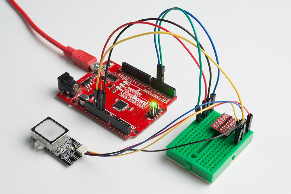
Option 1: Dedicated Bi-Directional Logic Level Converter (LLC)
It is recommended to use a dedicated bi-directional LLC for a reliable connection if you are using a 5V Arduino microcontroller. Assuming that you have soldered the header pins to the logic level converter, you would need to make these connections:
| Fingerprint Scanner (Pin #) | Logic Level Converter (Low Side) | Logic Level Converter (High Side) | 5V Arduino w/ Atmega328P |
|---|---|---|---|
| UART_TX (3.3V TTL) (Pin 1) | LV1 | HV1 | RX (pin 4) |
| UART_RX (3.3V TTL) (Pin 2) | LV4 | HV4 | TX (pin 5) |
| GND (Pin 3) | GND | GND | GND |
| Vin (3.3V~6V) (Pin 4) | LV | 3.3V | |
| HV | 5V |
After wiring the circuit, it should look like this:
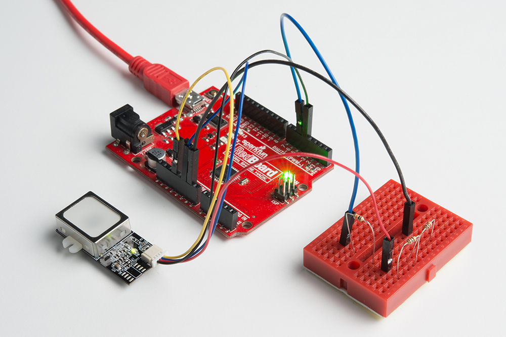
Option 2: Voltage Division w/ 3x 10kOhm Resistors
Otherwise, you could use 3x 10kOhm resistors to divide the voltage from a 5V Arduino down to 3.3V for the fingerprint scanner (FPS) similar to the "Uni-Directional" application circuit on our old logic level converter as shown below:

Below is the connection between the FPS, 5V Arduino, and resistors for voltage division:
| Voltage Divider | Fingerprint Scanner(Pin #) | Voltage Divider | 5V Arduino w/ Atmega328P |
|---|---|---|---|
| UART_TX (3.3V TTL) (Pin 1) | RX (pin 4) | ||
| GND < 10kOhm > 10kOhm |
UART_RX (3.3V TTL) (Pin 2) | 10kOhm | TX (pin 5) |
| GND | GND (Pin 3) | GND | GND |
| Vin (3.3V~6V) (Pin 4) | 5V |
Note: You can add the two 10kOhm resistors in series for 20kOhms.
After wiring the circuit up, it should look like this: