Experiment Guide for the SparkFun Tinker Kit
This Tutorial is Retired!
This tutorial covers concepts or technologies that are no longer current. It's still here for you to read and enjoy, but may not be as useful as our newest tutorials.
View the updated tutorial: Activity Guide for SparkFun Tinker Kit
 D___Run___
 Experiment 3: Driving an RGB LED
Introduction
You know what’s even more fun than a blinking LED? Changing colors with one LED. In this circuit, you’ll learn how to use an RGB LED to create unique color combinations. Depending on how bright each diode is, nearly any color is possible!
Parts Needed
You will need the following parts:
- 1x Breadboard
- 1x SparkFun RedBoard
- 1x Common Cathode RGB LED
- 3x 330Ω Resistors
- 6x Jumper Wires
Didn't Get the Tinker Kit?
If you are conducting this experiment and didn't get the Tinker Kit, we suggest using these parts:


Resistor 330 Ohm 1/6 Watt PTH - 20 pack
COM-11507
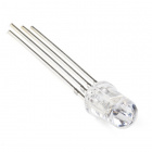
Introducing the Red Green Blue (RGB) LED
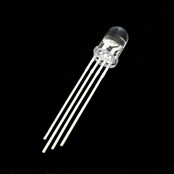
The Red Green Blue (RGB) LED is 3 LEDs in one. The RGB has four pins with each of the three shorter pins controlling an individual color: red, green or blue. The longer pin of the RGB is the common ground pin. You can create a custom colored LED by turning different colors on and off to combine them. For example, if you turn on the red pin and green pin, the RGB will light up as yellow.
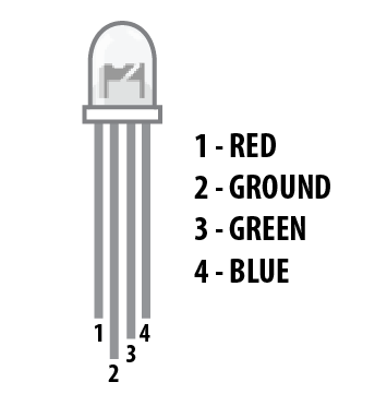
But which pin is which color? Pick up the RGB so that the longest pin (common ground) is aligned to the left as shown in the graphic below. The pins are Red, Ground, Green and Blue -- starting from the far left.
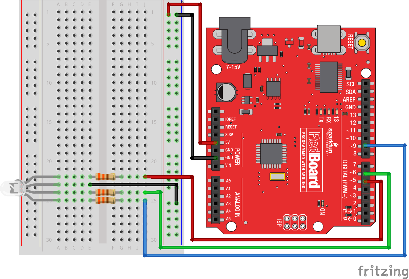
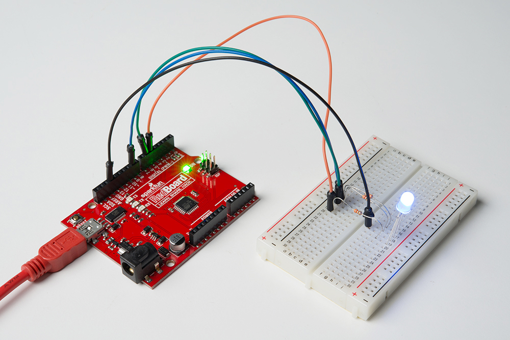
Hardware Hookup
Ready to start hooking everything up? Check out the wiring diagram and hookup table below to see how everything is connected.
| Polarized Components | Pay special attention to the component’s markings indicating how to place it on the breadboard. Polarized components can only be connected to a circuit in one direction. Polarized components are highlighted with a yellow warning triangle in the table below. |
Wiring Diagram for the Experiment
Open the Sketch
Open the Arduino IDE software on your computer. Coding in the Arduino language will control your circuit.
You can type out or copy and paste the following code into the Arduino IDE. Hit upload, and see what happens!
language:cpp
/*
SparkFun Tinker Kit
Example sketch 03

RGB LED

Make an RGB LED display a rainbow of colors!


This sketch was written by SparkFun Electronics,
with lots of help from the Arduino community.
Visit http://learn.sparkfun.com/products/2 for SIK information.
Visit http://www.arduino.cc to learn about Arduino.
*/

//create variables for pin numbers. We are making them constants here, because they       //never change.
const int RED_PIN = 5;
const int GREEN_PIN = 6;
const int BLUE_PIN = 9;

// How fast we plan to cycle through colors in milliseconds
int DISPLAY_TIME = 10;


void setup()
{
//set the three pin variables as outputs
pinMode(RED_PIN, OUTPUT);
pinMode(GREEN_PIN, OUTPUT);
pinMode(BLUE_PIN, OUTPUT);
}


void loop()
{
// We've written a custom function called mainColors() that steps
// through all eight of these colors. We're only "calling" the
// function here (telling it to run). The actual function code
// is further down in the sketch.
mainColors();


}


// Here's the mainColors() custom function we've written.
void mainColors()
{
// Off (all LEDs off):
digitalWrite(RED_PIN, LOW);
digitalWrite(GREEN_PIN, LOW);
digitalWrite(BLUE_PIN, LOW);

//wait 1 second
delay(1000);

// Red (turn just the red LED on):
digitalWrite(RED_PIN, HIGH);
digitalWrite(GREEN_PIN, LOW);
digitalWrite(BLUE_PIN, LOW);

//wait 1 seconds
delay(1000);

// Green (turn just the green LED on):
digitalWrite(RED_PIN, LOW);
digitalWrite(GREEN_PIN, HIGH);
digitalWrite(BLUE_PIN, LOW);

//wait 1 second
delay(1000);

// Blue (turn just the blue LED on):
digitalWrite(RED_PIN, LOW);
digitalWrite(GREEN_PIN, LOW);
digitalWrite(BLUE_PIN, HIGH);

//wait 1 second
delay(1000);

// Yellow (turn red and green on):
digitalWrite(RED_PIN, HIGH);
digitalWrite(GREEN_PIN, HIGH);
digitalWrite(BLUE_PIN, LOW);

//wait 1 second
delay(1000);

// Cyan (turn green and blue on):
digitalWrite(RED_PIN, LOW);
digitalWrite(GREEN_PIN, HIGH);
digitalWrite(BLUE_PIN, HIGH);

//wait 1 second
delay(1000);

// Purple (turn red and blue on):
digitalWrite(RED_PIN, HIGH);
digitalWrite(GREEN_PIN, LOW);
digitalWrite(BLUE_PIN, HIGH);

//wait 1 second
delay(1000);

// White (turn all the LEDs on):
digitalWrite(RED_PIN, HIGH);
digitalWrite(GREEN_PIN, HIGH);
digitalWrite(BLUE_PIN, HIGH);

//wait 1 second
delay(1000);
}
Code to Note
language:cpp
for (x = 0; x < 768; x++)
{}
A for() loop is used to repeat an action a set number of times across a range, and repeatedly runs code within the brackets {}. Here the variable "x" starts at 0, ends at 767, and increases by one each time ("x++").
language:cpp
if (x <= 255)
{}
else
{}
"If/else" statements are used to make choices in your programs. The statement within the parentheses ( ) is evaluated; if it's true, the code within the first brackets { } will run. If it's not true, the code within the second brackets { } will run.
What You Should See
You should see your LED turn on, but this time in new, crazy colors! If it doesn't, make sure you have assembled the circuit correctly and verified and uploaded the code to your board, or see the Troubleshooting section.
Troubleshooting
LED Remains Dark or Shows Incorrect Color
With the four pins of the LED so close together, it’s sometimes easy to misplace one. Double check that each pin is where it should be.
Seeing Red
The red diode within the RGB LED may be a bit brighter than the other two. To make your colors more balanced, use a higher ohm resistor.