Experiment Guide for the SparkFun Tinker Kit
This Tutorial is Retired!
This tutorial covers concepts or technologies that are no longer current. It's still here for you to read and enjoy, but may not be as useful as our newest tutorials.
View the updated tutorial: Activity Guide for SparkFun Tinker Kit
 D___Run___
 Experiment 10: Controlling a Motor with Inputs
Introduction
In Experiment 9 you used the H-Bridge to control a motor's direction and speed. The issue is that you had to hard code the direction and speed of your motor. Most applications that make use of a motor allow the user to control the speed and direction of the motor, much as you would your own car. In this experiment we will add two inputs and use them to control the direction and speed of your motor.
Are you ready to get your motor running? Let's go!
Parts Needed
You will need the following parts:
- 1x Breadboard
- 1x SparkFun RedBoard
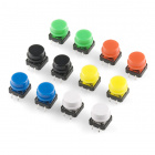
- 1x Push Button
- 1x 10K potentiometer
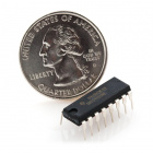
- 1x H-Bridge IC
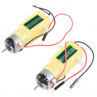
- 1x 48:1 ratio Gearmotor
- 20x Jumper Wires
Didn't Get the Tinker Kit?
If you are conducting this experiment and didn't get the Tinker Kit, we suggest using these parts:


Hardware Hookup
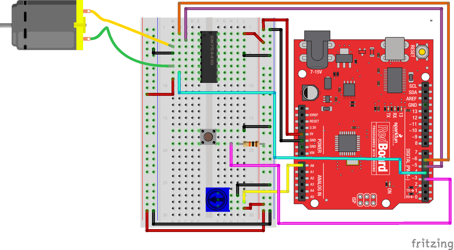
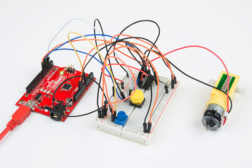
Ready to start hooking everything up? Check out the wiring diagram below to see how everything is connected.
| Polarized Components | Pay special attention to the component’s markings indicating how to place it on the breadboard. Polarized components can only be connected to a circuit in one direction. |
Wiring Diagram for the Experiment
Open the Sketch
Open the Arduino IDE software on your computer. Coding in the Arduino language will control your circuit.
You can type out or copy and paste the following code into the Arduino IDE. Hit upload, and see what happens!
language:cpp
/*
SparkFun Tinker Kit
Example sketch 10

H-Bridge Motor Controller with Inputs

  Use the inputs to manually set the direction and speed of a motor.


This sketch was written by SparkFun Electronics,
with lots of help from the Arduino community.
This code is completely free for any use.
Visit http://learn.sparkfun.com/products/2 for SIK information.
Visit http://www.arduino.cc to learn more about Arduino.
*/
 //define the two direction logic pins and the speed / PWM pin
 const int DIR_A = 5;
 const int DIR_B = 4;
 const int PWM = 6;

 //define the input pins
 const int switchPin = 3;
 const int potPin = 0;

 void setup()
 {
  //set all pins as output
  pinMode(DIR_A, OUTPUT);
  pinMode(DIR_B, OUTPUT);
  pinMode(PWM, OUTPUT);
  //set the switchPin as INPUT
  pinMode(switchPin, INPUT);
  }

void loop()
{
//read the value from the potentiometer and divide
//it by 4 to get a 0-255 range. Store the value in
//the speed variable
int speed = analogRead(potPin) / 4;

 //read the value of the switch and store it in the
 //direction variable.


//if the value of direction is HIGH drive forward at
//a speed set by the speed variable, else drive reverse
//at a speed set by the speed variable.
if (digitalRead(switchPin) == HIGH)
{
  forward(speed);
}
else
 {
 reverse(speed);
 }
}

//create a custom function that defines moving forward
//the forward() function accepts one parameter and that is
//the speed at which you want to drive forward (0-255)
 void forward(int spd)
 {
 //motor contoller direction pins set to forward
 digitalWrite(DIR_A, HIGH);
 digitalWrite(DIR_B, LOW);

  //write the speed by using the parameter of spd
 analogWrite(PWM, spd);
  }

//create a custom function that defines moving in reverse
//the reverse() function accepts one parameter and that is
//the speed at which you want to drive in reverse (0-255)
void reverse(int spd)
{
//set motor controller pins to reverse
digitalWrite(DIR_A, LOW);
digitalWrite(DIR_B, HIGH);

 //write the speed by using the parameter of spd
 analogWrite(PWM, spd);
 }
These big, scary functions take a single value as a parameter: speed. Each function then accepts that value and applies it to the analogWrite() function inside of the custom function. Custom functions are a great way to clean up your code and also make it more modular and useful in other applications. Watch out! You are halfway to writing your own library.
What You Should See
You should be able to control the motor's direction by flipping the SPDT switch and then the speed through the potentiometer. Go ahead and play with both inputs to make sure they both work and the motor is responding to those inputs.
Troubleshooting
Motor Only Spins in One Direction
Double check the wiring of your switch, but also double check your if() statement to make sure there isn't a semicolon after the statement.