ESP32 LoRa 1-CH Gateway, LoRaWAN, and the Things Network
 jimblom
Hardware Setup
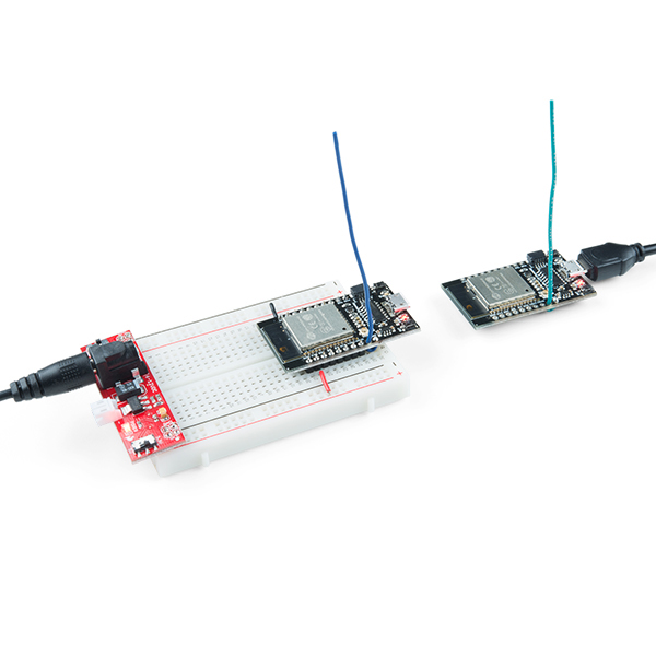
The ESP32 LoRa 1-CH Gateway includes almost everything you need to set up either a LoRaWAN gateway or device. You may not even have to solder anything to it to get started! Here's a quick rundown of the bare minimum you'll need to get started with the board.
Antenna
To allow the board to communicate with other LoRa devices, you'll need to add an antenna. This can be attached to either the U.FL connector or the ANT pin on the board.
The U.FL connector can be attached to an SMA to U.FL adapter cable, which can then be paired with a 900 MHz Duck Antenna.
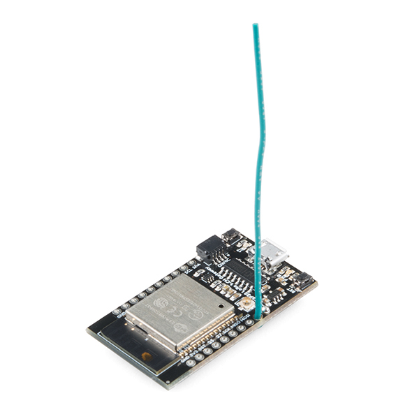
In lieu of a U.FL antenna, a strip of wire soldered to the ANT pin and sticking straight up will work as well. Here are wire lengths for quarter-wave antennas at 915MHz and 434MHz:
| Frequency | Length (inches) | Length (mm) |
| 915 MHz | 3.07" (3 + 1/16") | 78mm |
| 434 MHz | 6.47" (6 + 1/2") | 164mm |
Powering the Board
The board is nominally powered via the on-board micro-USB connector. The other end of your USB cable can be plugged into either a computer, wall adapter, or a USB battery pack.
Alternatively, the board can be powered using a regulated 3.3V power supply. This supply should be applied to the 3.3V and GND pins.