E-Textiles ISTE Workshop
 Gella
Gella Introduction
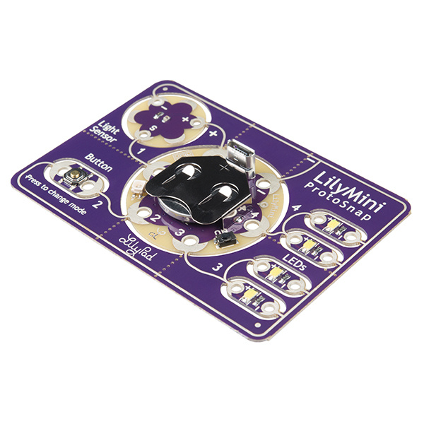
The LilyMini ProtoSnap is a great way to learn basic programming and use those skills to make fun LilyPad sewable electronics projects. Whether you've completed all the projects in the LilyPad Sewable Electronics Kit and are looking to reprogram your Night-Light Pennant project, or you've purchased a brand new LilyPad LilyMini ProtoSnap, this guide will help you learn to write your own custom programs with Arduino.
Who Is This Guide For?
This guide was created for beginners looking for an introduction to Arduino programming through fun, structured activities. Every activity will show off simple programming techniques that will be useful in your own projects.
If you already know a bit about Arduino, you can jump right into the more technical documentation in Programming the LilyMini. And if you'd rather not write your own code, the LilyMini ProtoSnap comes pre-loaded with fun code that you can use in your projects. Check out the LilyMini ProtoSnap Hookup Guide for more information.
If you have snapped the board apart, all is not lost. You can re-make the connections using alligator cables. You can use the images of the Protosnap board throughout this guide as a reference to what connects where.
If you want to do the activities in this guide with a LilyMini that's already sewn into a project, that's fine too. Your project should ideally use the same parts contained in the LilyMini Protosnap. You may also need to change the pin numbers in the example code to match the pins numbers that were used in your project.
Tools and Materials
In addition to a LilyMini ProtoSnap, you will need a computer (Windows 10 or Mac) with an internet connection, and a micro-B USB cable. This is a common cable used by many cell phones, so you may have one already. Double check that it is not labeled 'Power Only' as these type of cables will not transmit any of the data needed during programming to the LilyMini board.
Suggested Reading
If you are brand new to Arduino and the LilyMini, take a look at these tutorials for more information on the board and how to install the LilyMini in the Arduino environment:
What is an Arduino?
Installing Arduino IDE
LilyMini ProtoSnap Hookup Guide
Setting Up Arduino
Note that the LilyMini only works with Arduino version 1.8 or higher and Windows 10 or Mac computers (for now).
What Is Arduino?
Arduino is a combination of inexpensive hardware and free software that allows you easily create "smart" projects limited only by your imagination. The LilyMini is one of many Arduino-compatible microcontrollers (a tiny, self-contained computer). It is part of the LilyPad system, which includes a variety of Arduino-programmable boards and components.
The LilyMini was designed to fill the need for something more easily programmed than the smaller LilyTiny, while being less complex and expensive than the larger LilyPad boards like the LilyPad Arduino USB. It's a great tool for the classroom, and an inexpensive and fun way to learn programming while making craft projects.
What is a Program?
A program is a set of instructions that a computer carries out. The computer reads each line of code (written in a language that the computer understands), carries out the instructions, and goes on to the next line. Depending on decisions the computer is asked to make, the computer may jump forward or backwards in the set of instructions.
Arduino uses a simplified version of a computer language called C. Programs are written in text, using special words called commands that the computer understands. Arduino hides most of the complexity of programming a computer, leaving the fun part to you.
Once you write your program, you'll need to transfer it to the board so it can run. Arduino uses an elegant system that uploads code from your computer to the board over USB. Once it's on the board, your program will stay there (even after you turn off the power) until you replace it with a new program.
Programs let you customize the board to do what you want it to do.
Ready to get started? Start up the Arduino software to follow along with the rest of this guide.
Connect the LilyMini to Your Computer
Before you can upload a program to the LilyMini, you will need to connect it to a computer using a micro-B USB cable. Connect the small end of the USB cable to the USB port on the LilyMini. It will only fit one way, and should click in securely.
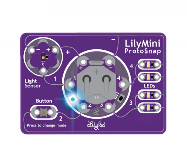
Next, plug the other end of the USB cable into an available port on your computer. The LilyMini's built-in RGB LED should fade from off to green to indicate that it's powered on. If it doesn't, press the small black "ON" button on the LilyMini to turn it on. The LilyMini must be turned on to program it.
Select the LilyMini in Arduino
Arduino knows how to program many different boards. We now need to tell it that we'll be programming a LilyMini. In Arduino, select the Tools > Board menu. This will bring up a long list of Arduino boards. Scroll down to find LilyPad LilyMini in the SparkFun SAMD section, and click on it. A check mark will appear when the board is selected.
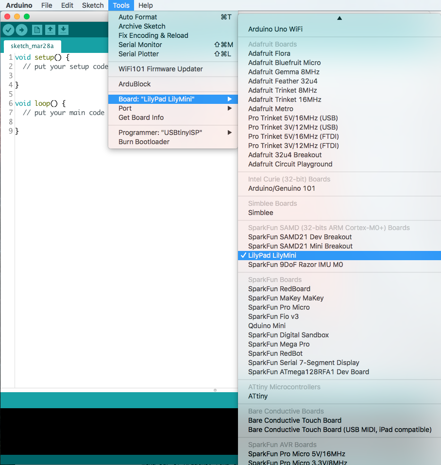
If you do not see the LilyMini in the list, double check that you did all the setup steps in the Programming the LilyMini tutorial.
Selecting a Serial Port
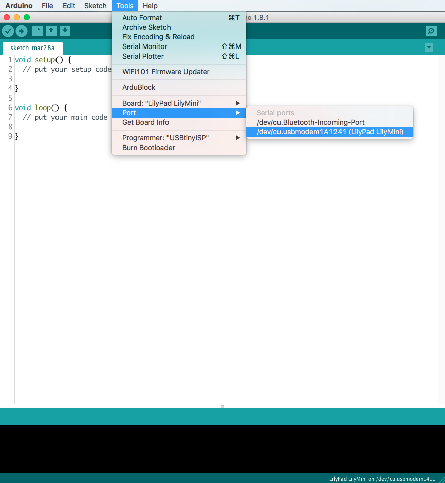
Next, Arduino needs to know which USB port the LilyMini is plugged into. In the same Tools menu, select Port and look at the list of available devices. Find the one that says "LilyPad LilyMini" next to it, and click on it.
Activity 1: Blinking LEDs
It's time to upload your first program to the LilyMini! In this activity, you'll learn how to blink any of the many LEDs built into the LilyMini ProtoSnap.
Open the Blink Example
A handy feature of Arduino is that it contains many built in programming examples. We've put the example code for these activities under File > Examples > LilyMini_Guide:
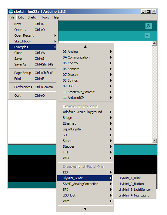
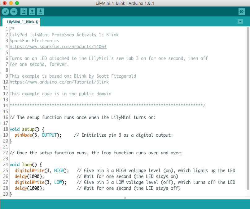
From the LilyMini_Guide submenu, open LilyMini_1_Blink. A window should pop up with that program:
Alternatively, you can copy and paste the following code into Arduino. Be sure to completely clear the window first.
/*
LilyPad LilyMini ProtoSnap Activity 1: Blink
SparkFun Electronics
https://www.sparkfun.com/products/14063

Turns on an LED attached to the LilyMini's sew tab 3 on for one second, then off
for one second, forever.

This example is based on: Blink by Scott Fitzgerald
https://www.arduino.cc/en/Tutorial/Blink

This example code is in the public domain

******************************************************************************/

// The setup function runs once when the LilyMini turns on:

void setup() {
  pinMode(3, OUTPUT);     // Initialize pin 3 as a digital output:
}

// Once the setup function runs, the loop function runs over and over:

void loop() {
  digitalWrite(3, HIGH);   // Give pin 3 a HIGH voltage level (on), which lights up the LED
  delay(1000);             // Wait for one second (the LED stays on)
  digitalWrite(3, LOW);    // Give pin 3 a LOW voltage level (off), which turns off the LED
  delay(1000);             // Wait for one second (the LED stays off)
}
Uploading your Program to the LilyMini
To run this program on your LilyMini, click the round icon with the right arrow in it at the top of the window. Arduino will check the program for errors (and stop if it finds any), compile the code, converting it from human-readable text to machine readable instructions, and transfer it over the USB cable to the LilyMini.
While it's transferring, the LilyMini's RGB LED will blink different colors, and when the transfer is finished, the code will automatically begin running.
What You Should See
You should see the two LEDs attached to sew tab 3 blink on and off.
In the LilyMini ProtoSnap, the white LEDs are connected to the sew tabs in pairs; two to sew tab 3, and two to sew tab 4. This is known as a parallel circuit. If you turn on one of those sew tabs, you'll turn on both LEDs.
You may remember this type of circuit layout if you built the Illuminated Mask project. In that project, three LEDs shared the same power source.
Understanding Your Program
There's a lot to cover here, but don't get overwhelmed. This will all become second nature soon.
Every Arduino program has two specific functions (named sections of code): one named setup() and one named loop(). (You can add as many of your own functions as you like, but every Arduino program will have at least those two).
The setup() function runs once when your program starts up. It's a good place to put initialization steps that need to happen before the rest of your program runs. Often you'll configure the hardware to match your specific project here, telling pins to be inputs or outputs, etc.
The other function, loop() runs after setup() finishes, and runs over and over, forever. This is where most of your code that completes tasks will be stored. The fact that it loops is very handy - if you blink an LED once in loop(), it will blink on and off forever because loop() runs over and over.
Syntax
Computers are fast, but not very smart. They can only understand specific instructions written in a very standard way. Syntax is the set of rules and structure for a computer (or any other) language. For example, you'll notice that each line of code ends with a semicolon - ;. Much like the period at the end of a sentence, the semicolon helps the computer determine where each line of instructions ends.
When you start writing your own code it's easy to forget the semicolon, but the Arduino IDE will helpfully tell you with a red error message.
Configuring the Electrical Connections
Although we call the electrical connections on LilyPad products "sew tabs", the common name for such a connections is a "pin". Arduino uses the word "pin" to refer to electrical connections between the board running the code, and the outside world. There are a number of commands that let you do whatever you want with these pins.
Before you can use one of the LilyMini's pins or sew tabs, it needs to be configured as either an input or an output. This is from the point of view of the LilyMini: outputs are used to control things like LEDs, speakers, motors, etc. Inputs are used to gather information from the outside world, such as buttons, switches, and various sensors.
We use a built-in function called pinMode() to configure pins as inputs or outputs. pinMode() takes two parameters (pieces of information within the parentheses): the pin you'd like to affect, and whether you want that pin to be an INPUT or an OUTPUT. For example, the command:
pinMode(3, OUTPUT);
Tells the board to set pin 3 as an OUTPUT.
Commanding Pins
To actually send voltage to an output pin requires an additional command called digitalWrite(). DigitalWrite() takes two parameters; the pin number you'd like to affect, and whether you want the pin to be "on" (outputting voltage) or "off" (connected to ground). Instead of saying "on" and "off", we say "HIGH" and "LOW". For example, if you connect sew tab 3 to a LED, and want to turn the LED on, you would use the command:
digitalWrite(3, HIGH);
If you want to turn the LED off, you'd use the command:
digitalWrite(3, LOW);
Slowing Things Down
To make an LED blink, you turn it on (HIGH) then off (LOW), and repeat. This is exactly what our code is doing. However, the microcontroller operates so quickly (48 million instructions per second!) that to our eyes those changes would appear to be instantaneous, and the LED would look like it's always on. To slow things down, the program uses a handy command called delay() which stops and waits a certain amount of time:
delay(1000);
The delay() command takes one parameter, the number of milliseconds to wait. There are 1000 milliseconds in one second, so the above example will pause for one second. When you're blinking LEDs, don't forget that you will also need to delay() while the LED is turned off. This is why there are two delay()s in our code.
Further Reading:
The Arduino website has a great reference page for every available Arduino command. Here are the entries for the commands we just used:
- digitalWrite on Arduino Reference
- pinMode on Arduino Reference
- delay on Arduino Reference
Understanding Your Circuit
When you work with the LilyMini or any Arduino board, you're working with a combination of hardware and software. Neither one will work without the other! You write code that does various things to the pins, then you build projects that connect the pins to LEDs, sensors, speakers, etc.
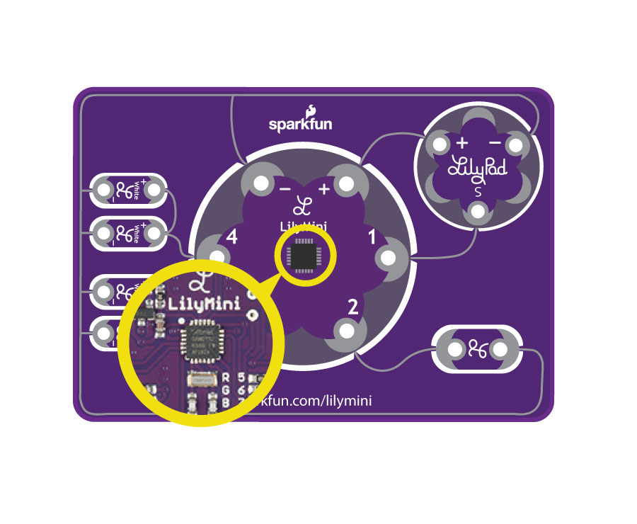
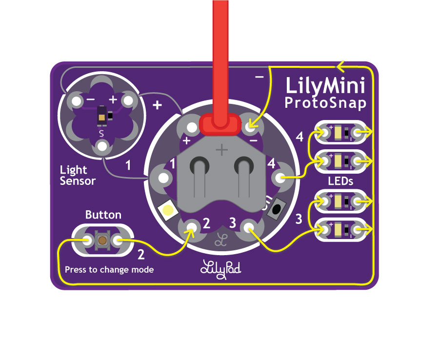
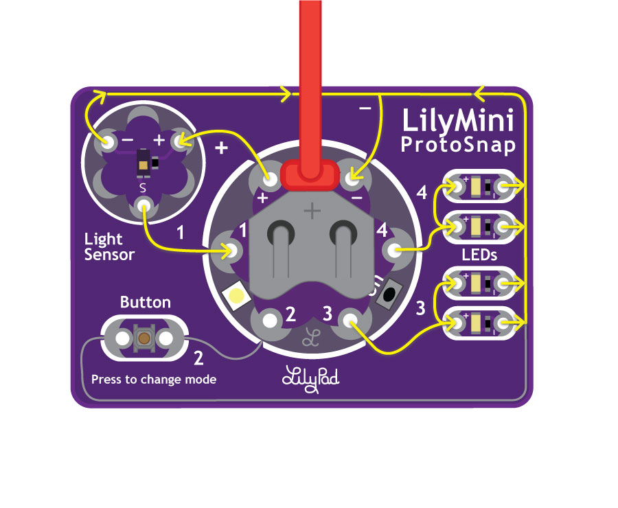
If you turn the ProtoSnap board over, you'll see the SAMD11 chip that stores your uploaded code and is the 'brains' of the LilyMini. Follow the purple lines coming from the chip's metal pins to see how they electrically connect to components on the LilyMini and its sew tabs, and further out into the larger ProtoSnap board. The conductive metal lines that connect everything together are called traces.
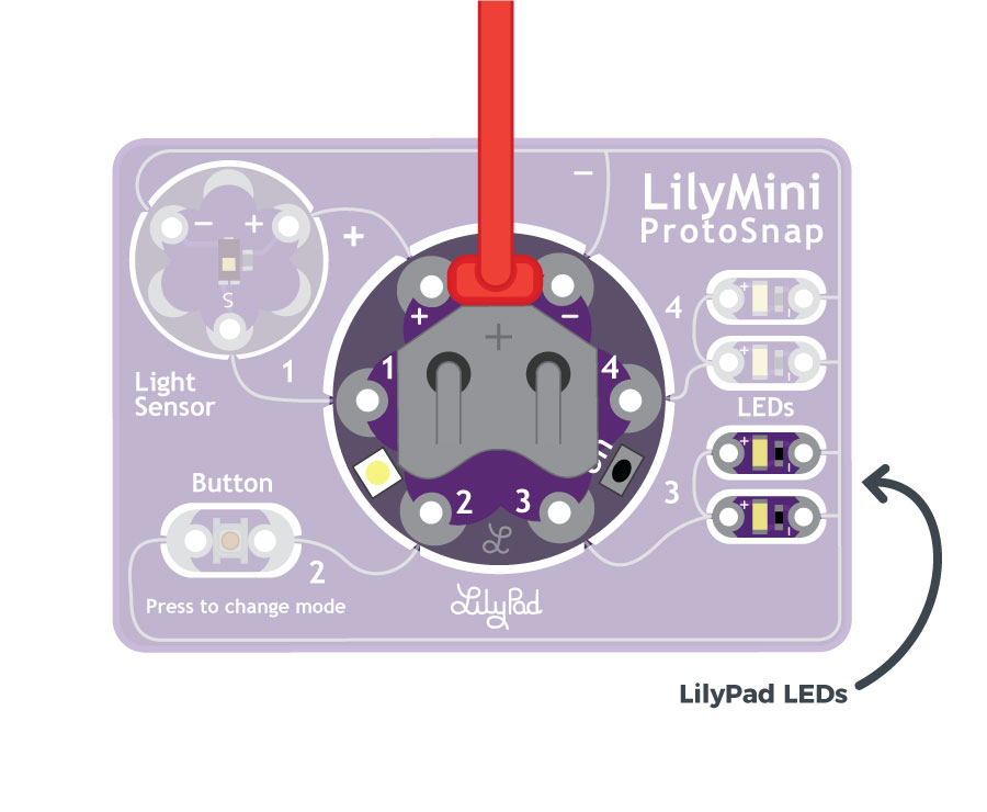
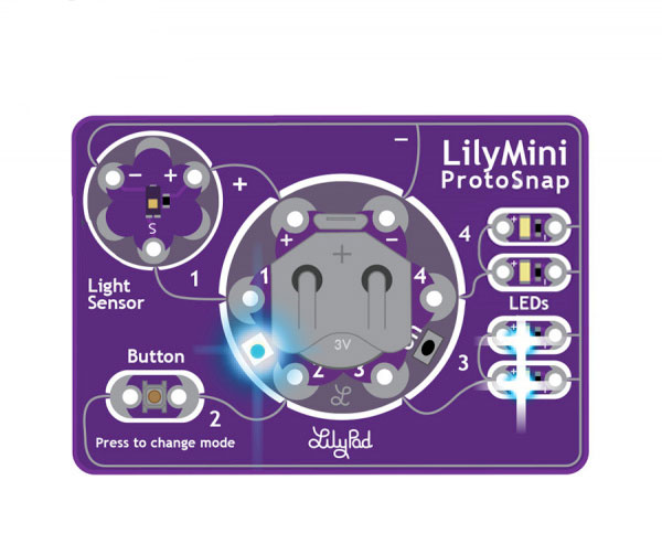
In the LilyMini ProtoSnap, sew tab 3 is connected to two white LEDs. The other side of the LEDs is connected to ground, which wraps around to the "-" sew tab on the LilyMini, completing the circuit. See the illustration below for a representation of current flowing through the LilyMini ProtoSnap.
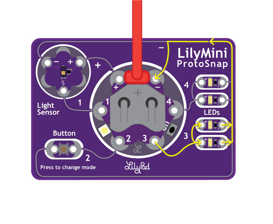
In the blink program you just uploaded, the digitalWrite(3,HIGH); command applies voltage to sew tab 3, which lights up the LEDs. The digitalWrite(3,LOW); command turns off the voltage, which turns off the connected LEDs.
While the ProtoSnap board is in one piece, you can write programs that make all the connected pieces work together. Later on when you have your code working the way you want, you can snap the board apart, build your project, and re-connect everything with conductive thread. But for now, leave everything connected so we can do the other exercises in this guide.
Challenges and Going Further
- Can you change the code to control the LEDs connected to sew tab 4 on the LilyMini?
- What happens when you change the value in the delay() function?
- Can you add some lines of code so that both pairs of LEDs on sew tabs 3 and 4 light up simultaneously?
- How fast can you get the LEDs to blink before you can no longer tell they are blinking?
Activity 2: Using the LilyPad Button
In the last activity, you learned about output - making the LilyMini control things like LEDs. In this activity we'll learn about input, which lets the LilyMini react to the world around it. This is a very powerful concept; it's what has made computers so useful in our daily lives.
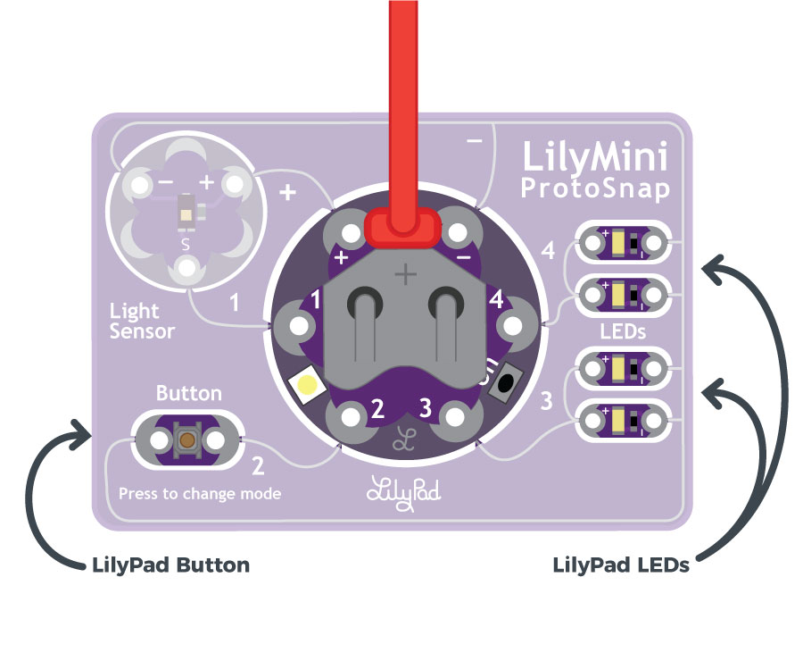
In this activity, we'll make the LilyPad button in the lower left of the ProtoSnap control the LEDs. We'll show you how to tell if a button connected to the LilyMini is being pressed, and then how to decide whether to light up the LEDs or not. Unlike simple projects where power is being turned on an off by a button (like the Light-Up Plush), we'll be doing this with software, which allows you to make more advanced decisions about what to do at the press of a button or other input.
Open the Button Example
Open the file named LilyMini_2_Button.ino
Alternatively, you can copy and paste the following code into Arduino. (Be sure to clear the window first). Click the upload button (the round button with the right arrow), and see what happens!
/*
LilyPad LilyMini ProtoSnap Activity 2: Button
SparkFun Electronics
https://www.sparkfun.com/products/14063
Read a button (digital input) on pin 2
Turn on the LED when pressed, and off when released.
This example is based on InputPullupSerial code by Scott Fitzgerald
http://www.arduino.cc/en/Tutorial/InputPullupSerial
This example code is in the public domain
******************************************************************************/
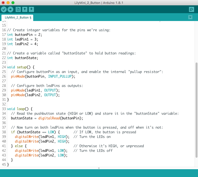
// Create integer variables for the pins we're using:
int buttonPin = 2;
int ledPin1 = 3;
int ledPin2 = 4;
// Create a variable called "buttonState" to hold button readings:
int buttonState;
void setup() {
// Configure buttonPin as an input, and enable the internal "pullup resistor":
pinMode(buttonPin, INPUT_PULLUP);
// The pullup is a small internal resistor between the sewtab and HIGH voltage.
// This weakly "pulls up" the input to HIGH if the button is not being pressed.
// This keeps the input from "floating" (randomly reading either HIGH or LOW)
// when the button is not being pressed.
// Configure both ledPins as outputs:
pinMode(ledPin1, OUTPUT);
pinMode(ledPin2, OUTPUT);
}
void loop() {
// Read the pushbutton state (HIGH or LOW) and store it in the "buttonState" variable:
buttonState = digitalRead(buttonPin);
// Note that LOW = pressed and HIGH = released, the opposite of what you might expect.
// This is because the button is attached to ground, which is the LOW voltage level.
// We use the pullup to weakly "pull up" the button to HIGH when it's not being pressed.
// When the button is pressed, the strong ground signal overwhelms the weak pullup signal.
// Now turn on both ledPins when the button is pressed, and off when it's not:
if (buttonState == LOW) { // If LOW, the button is pressed
digitalWrite(ledPin1, HIGH); // Turn the LEDs on
digitalWrite(ledPin2, HIGH);
} else { // Otherwise it's HIGH, or unpressed
digitalWrite(ledPin1, LOW); // Turn the LEDs off
digitalWrite(ledPin2, LOW);
}
// The if statement turns the LEDs off (LOW) when the button is not being pressed (HIGH),
// and on (HIGH) when the button is pressed (LOW).
}
What You Should See
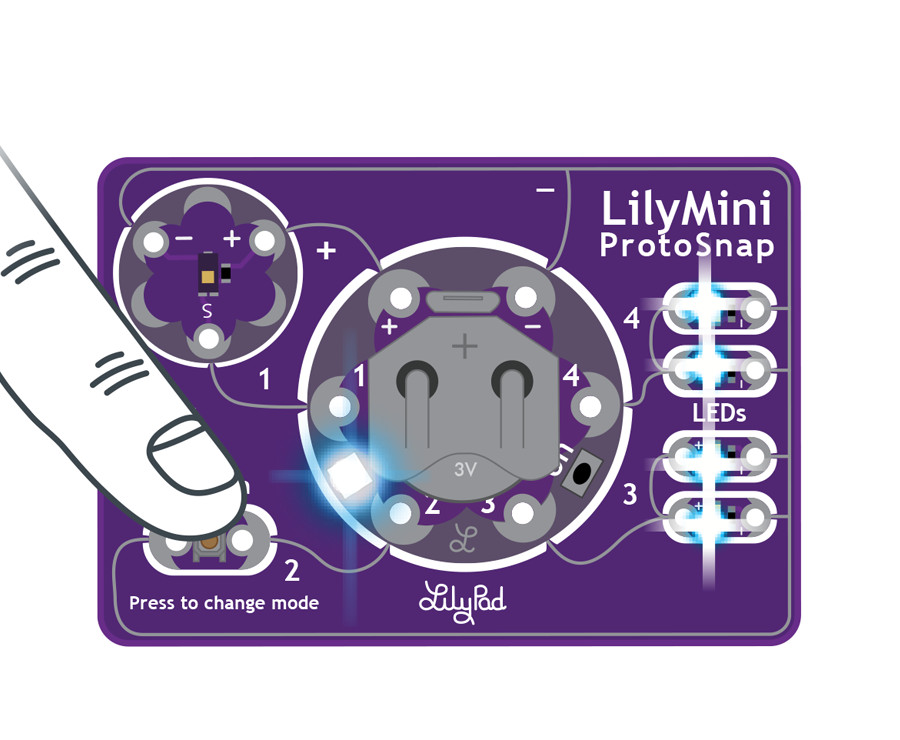
When you press the button on the LilyMini ProtoSnap, the LEDs should light up.
Understanding Your Program
int buttonPin = 2;
int ledPin = 3;
int ledPin = 4;
This example has a few additional lines of code before the setup and loop sections. Rather than assign pin numbers directly in pinMode or digitalWrite, you can create variables to store names or data. This makes your code easier to read and easier to change.
Everywhere buttonPin is used, the program will replace it with 2. If you decide to use a different pin to connect the button to in a future project, let's say tab 3, then you can replace the 2 with 3 at the start of your program instead of going through your code and manually replacing each instance.
You can see the program also uses variables to name the LEDs connected to sew tabs 3 and 4 of the LilyMini - ledPin1 and ledPin2. Notice how the buttonState does not have a number assigned to it. This variable will be used dynamically - the values assigned to it will change each time you press the button.
Before you use a variable, you must declare it - tell the computer what type of data it will be storing. Notice the "int" before all the variables used in this program - int is short for integer, which is defined as a whole number that can be positive or negative. In addition to declaring the name and type of a variable, we can also intialize it, or give it a starting value that you can change later or leave alone. For more information on all the variables Arduino understands, see their Language Reference Page.
pinMode(buttonPin, INPUT_PULLUP);
Before you can use any of the LilyMini's pins, you need to set whether it is an INPUT or OUTPUT. When controlling LEDs, we use OUTPUT, because we're sending voltage out of the LilyMini to the LEDs. This time we're reading voltage from an external component (a button), so we'll use INPUT_PULLUP.
When buttons and switches attached to an input are turned off, the input is not really connected to anything, which we call "floating". The input will not be HIGH or LOW, and will cause strange input readings. For this reason, we tell the LilyMini to connect a small internal resistor between the input pin and +. This "pulls up" the input to a solid HIGH when it's not connected to anything, which makes switches and buttons work properly. We call this a pullup resistor.
If a switch or button in your program ever behaves strangely, double-check that you used INPUT_PULLUP.
buttonState = digitalRead(buttonPin);
The next piece of code does the actual input - it reads the state of buttonPin and stores it the buttonState variable. This will be LOW if the button is pressed, and HIGH if it's released (more on this later).
Using if statements
The true power of tiny computers is that they can make decisions based on input. The if statement lets you do this. The structure of an if statement is:
Something to check
if (buttonState == LOW)What to do if it's true
{digitalWrite(ledPin1, HIGH);digitalWrite(ledPin2, HIGH);}(Optional) what to do if it's false
else{digitalWrite(ledPin1, LOW);digitalWrite(ledPin2, LOW);}
Here are a few notes about the above code:
In the
ifstatement, you can use standard math symbols to check if numbers are greater than, less than, or equals. But note that for equals, we're using two equals symbols==. This is because a single equals is already used for assignment likex = 3. To keep the computer from getting confused, we use two equals for comparisons likeif (x == 3).The
ifstatement usually lets you run one command if the statement is true, and (optionally) one command if the statement is false. If you want to run more than one command (like we did), you can put as many commands as you want in a set of curly brackets{ }.
Further Reading:
- Pull-up Resistors on SparkFun tutorials
- Declaring Variables on Arduino Reference
- If...else on Arduino Reference
Understanding Your Circuit
In the Blink example, you used digitalWrite to control whether the LilyMini was sending voltage to a sew tab or not. Now we're using digitalRead to checks a sew tab to see if voltage is present on it or not.
The button works by electrically connecting the two sides of the button board when you press it, and disconnecting them when you release it. The button is an example of a momentary switch – it is only active when an action is applied. On the ProtoSnap, the button is connected to sew tab 2. When you make your own projects, you could make any of the sew tabs an input, and connect them to buttons, switches, or other input devices.
One thing to note is that the other side of the button is connected to ground (marked as - or "minus" on the board). This means that when you press the button, sew tab 2 will be connected to ground, which reads as LOW, and when you release it, the pullup resistor will make it read as HIGH... This may be the opposite of what you expect! But since the if statement lets you check if something is true or false, and do whatever you want for either result, it's easy to make it do whatever you want. Try it!
Further Reading:
Challenges and Going Further
- Can you change the code to make both sets of LEDs light up?
- Can you change the code so that LEDs light up alternately (one LED lights up when pressed while the other turns off)?
- Can you add a delay so that the LED blinks when the button is held down?
Activity 3: Reading a Sensor
In the activities up until now, we've dealt with input and output that is either on or off, or in Arduino, HIGH or LOW. These are called digital signals because they only have two states - on and off. But the LilyMini and other microcontrollers can also send and receive what are called analog signals, which provide all the intermediate values between on and off. Analog signals are especially useful for sensors that look at the real world, like temperature, which can be many more values than just HOT or COLD.
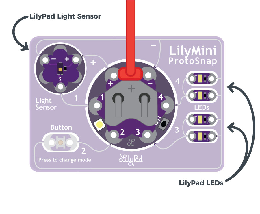
In this activity, we'll make use of the LilyPad Light Sensor in the upper-left hand corner of the ProtoSnap. It provides an analog output that we'll use to measure the amount of light present. Then we'll use our old friend the if statement to make a decision as to whether it's dark enough to turn on the LEDs as a night light.
We'll also show you how to use Arduino's Serial Monitor feature, which lets you send text and data from the LilyMini to your computer. This provides a new way to interact with the LilyMini that can make writing and debugging your programs much easier.
Open the Light Sensor Example
Open the file LilyMini_3_NightLight.ino
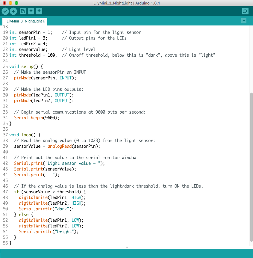
Alternatively, you can copy and paste the following code into Arduino. Hit upload, and see what happens!
/*
LilyPad LilyMini ProtoSnap Activity 8: Night-Light with Light Sensor
SparkFun Electronics
https://www.sparkfun.com/products/14063

Read the ambient light levels from the LilyPad Light Sensor attached to sew tab 1.
Turn on the LEDs on sew tabs 3 and 4 when the light level falls below a certain level.
Also print the light level to the serial monitor window.

This example is based on: If Statement by Tom Igoe
http://www.arduino.cc/en/Tutorial/IfStatement

This example code is in the public domain

******************************************************************************/

// Declare the variables we'll be using

int sensorPin = 1;    // Input pin for the light sensor
int ledPin1 = 3;      // Output pins for the LEDs
int ledPin2 = 4;
int sensorValue;      // Light level
int threshold = 100;  // On/off threshold, below this is "dark", above this is "light"

void setup() {

  // Make the sensorPin an INPUT:

  pinMode(sensorPin, INPUT);

  // Make the LED pins outputs:

  pinMode(ledPin1, OUTPUT);
  pinMode(ledPin2, OUTPUT);

  // Begin serial communications at 9600 bits per second:

  Serial.begin(9600);
}

void loop() {

  // Read the analog value (0 to 1023) from the light sensor:

  sensorValue = analogRead(sensorPin);

  // Print out the value to the serial monitor window
  // (Click the magnifying glass icon to open it)

  Serial.print("Light sensor value = ");
  Serial.print(sensorValue);
  Serial.print("  ");

  // If the analog value is less than the light/dark threshold, turn ON the LEDs,
  // otherwise turn them off. Also print out what we decided:

  if (sensorValue < threshold) {
    digitalWrite(ledPin1, HIGH);
    digitalWrite(ledPin2, HIGH);
    Serial.println("dark");
  } else {
    digitalWrite(ledPin1, LOW);
    digitalWrite(ledPin2, LOW);
    Serial.println("bright");
  }
}
What You Should See
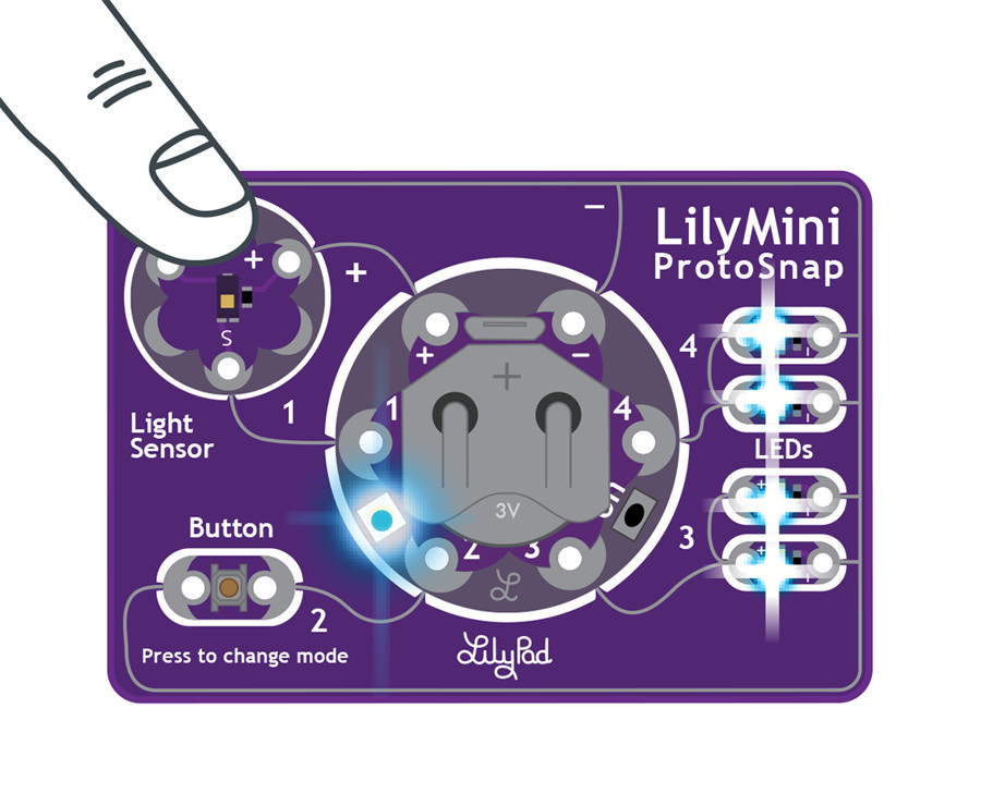
Cover the light sensor with your hand or an object to reduce the light that the sensor is reading. At a certain point the white LEDs should turn on. Remove your hand to allow more light to hit the sensor, and the white LEDs will turn off.
Next, click on the magnifying glass icon in the upper right of Arduino. This will open the Serial Monitor window. The Serial Monitor window shows everything that your program sends with a Serial.write() command. This program writes the values it's reading from the light sensor, and whether the value is above or below the light/dark threshold we've set. Observe the range of values that scroll by on the window. How low (dark) can you make the area above the sensor? What is the average brightness in the room?
Understanding Your Program
sensorValue = analogRead(sensorPin);
In the activity where you used the LilyPad Button, the program used digitalRead to read the button state as HIGH or LOW. The LilyPad Light Sensor functions differently; instead of being either on or off, it outputs a varying voltage depending on the light level. In the dark, the light sensor will output around 0 volts. In very bright light, it will output around 3 volts.
The LilyMini reads this varying voltage using the command analogRead. AnalogRead converts voltages from 0 to 3.3 volts, into the range 0 to 1023. Like the button examples, your program stores the reading in a variable (called sensorValue) to use later.
int threshold = 100;
As we just saw, our program will read the light sensor and return a number in the range 0 to 1023. If we want to make a night light, we need to decide where on this scale "dark" is. To do this, we've declared a variable named threshold, and given it a value of 100. We'll compare each light sensor reading to this threshold; if it's below the threshold ("dark") we'll turn on the LEDs. If it's above the threshold, we'll turn off the LEDs ("light"). The advantage of using a variable for the threshold, is that it's easy to change. If you think your night light is turning on when it's too light out, just reduce the number stored in threshold and try again.
Serial.begin(9600);
This command starts a serial communication connection between your LilyMini and Arduino software to allow you to view information as your program runs. ("9600" is the speed at which the serial communication occurs.) In this program, you'll use the Serial Monitor to view the light-level values as they are read from the light sensor. This will help you decide where to set the light/dark threshold.
You can read more about Arduino's Serial Communication functions at the Arduino website.
Serial.print("Light sensor value = ");
Serial.print(sensorValue);
These lines of code send data to the serial monitor window. Note that the first Serial.print prints a text label (to print text, enclose it with double-quotes), and the second prints the actual value. You can string together Serial.print statements in this way to label and format data just the way you want it.
if (sensorValue < threshold)
This if statement uses a < symbol instead of an == sign as in the button example. It compares the value in sensorValue to the predetermined threshold. If the number in sensorValue is less than the number in threshold, the code in the first section of the if statement runs (it's dark, so we turn on the LEDs). if the number in sensorValue is greater than the number in threshold, the code in the else section of the statement runs (it's light so we turn off the LEDs).
Serial.println("Dark");
Serial.println("Light");
In addition to turning the LEDs on and off, we've added some more Serial statements to the if statement. But wait! These are a little different.
There are two similar Serial print commands: Serial.print and Serial.println. Both of them will send numbers or text to the serial monitor windows. The difference between them is that Serial.println will append a new line (or if you're older, a carriage return) to whatever it prints, causing the next print statement to start on a new line. This lets you neatly format your Serial output.
Another benefit of adding these serial commands within the if statement is that it allows you to debug your code and make sure everything is working even if your LEDs are not connected. Don't hesitate to put Serial.print statements in your code to help debug it.
Further Reading:
- analogRead on Arduino Reference
- Conditionals in if statements on Arduino Reference
- Serial.print on Arduino Reference
- Serial.println on Arduino Reference
Understanding Your Circuit
Unlike the button, the light sensor has active circuitry on it. It needs to have power to operate, so it has (+) and ground (-) tabs connected to power on the LilyMini, and it has a third output tab labeled S for signal. The signal tab is connected to sew tab 1 on the LilyMini.
This sensor outputs a voltage that varies with the ambient light level. It ranges from 0 volts (very dark) to 3.3V (very bright). The output voltage is sent to the LilyMini, where it is measured by an analog to digital converter (ADC). The ADC returns a number from 0 (no voltage) to 1023 (maximum voltage). The LilyMini can measure analog voltages on any of its sew tabs.
Further Reading:
Challenges and Going Further
- Can you write some code so the LED blinks when it gets dark?
- Can you write some code so that the RGB shows one color when ‘light’ and one color when ‘dark’?
- Can you assign colors to different ranges of darkness?
Going Further: RGB LED
In this activity we'll control a colorful LED!
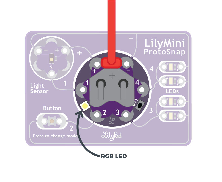
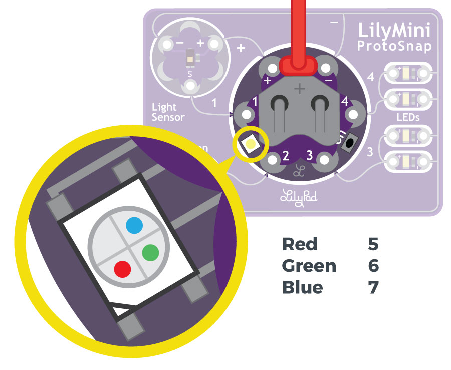
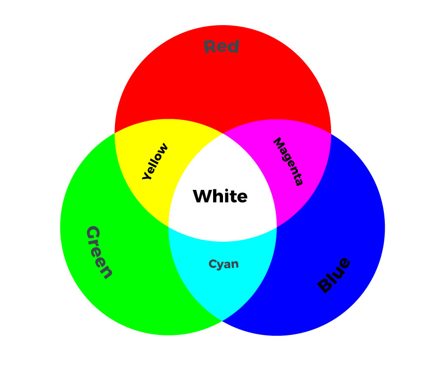
You probably noticed that your LilyMini has a built-in LED that it uses to tell you when it's turning on or off. This LED is special - it is actually 3 LEDs in one package - a red, a green, and a blue. This is why it's called a RGB (Red Green Blue) LED. The RGB LED can create many more colors than just red green and blue - When you turn on combinations of colors, they mix to create new colors!
You can control this LED from your code like the white LED pairs you used in activities 1 and 2. Just like the sew tabs numbered 1 through 4 are able to be controlled by your program, the RGB LED is also attached to pins on the LilyMini: the red LED is pin 5, the green LED is pin 6, and the blue LED is pin 7.
Open the Color Mixing Example
Open the file named LilyMini_4_Color Mixing
Alternatively, you can copy and paste the following code into Arduino (be sure to erase everything already in the editing window first). Hit upload, and see what happens!
/*
LilyPad LilyMini ProtoSnap Activity 4: Color Mixing
SparkFun Electronics
https://www.sparkfun.com/products/14063
Make an RGB LED display a rainbow of colors!
An RGB LED is actually three LEDs (red, green, and blue) in
one package. When you run them at different brightnesses,
the red, green and blue mix to form new colors.
The LilyMini has a built-in RGB LED between sew tabs 1 and 2.
Red - pin 5
Green - pin 6
Blue - pin 7
This example is based on:
This example code is in the public domain
******************************************************************************/
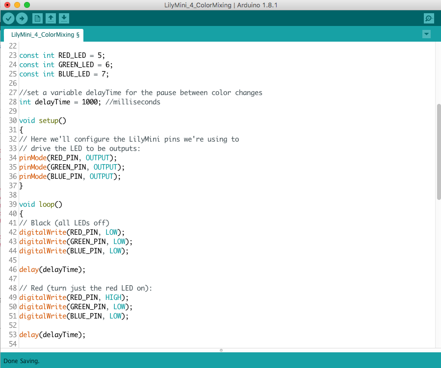
const int RED_LED = 5;
const int GREEN_LED = 6;
const int BLUE_LED = 7;
//set a variable delayTime for the pause between color changes
int delayTime = 1000; //milliseconds
// This variable controls how fast we loop through the colors.
// (Try changing this to make the fading faster or slower.)
void setup()
{
// Here we'll configure the LilyMini pins we're using to
// drive the LED to be outputs:
pinMode(RED_PIN, OUTPUT);
pinMode(GREEN_PIN, OUTPUT);
pinMode(BLUE_PIN, OUTPUT);
}
void loop()
{
// The first way is to turn the individual LEDs (red, blue,
// and green) on and off in various combinations. This gives you
// a total of eight colors (if you count "black" as a color).
// Black (all LEDs off)
digitalWrite(RED_PIN, LOW);
digitalWrite(GREEN_PIN, LOW);
digitalWrite(BLUE_PIN, LOW);
delay(delayTime);
// Red (turn just the red LED on):
digitalWrite(RED_PIN, HIGH);
digitalWrite(GREEN_PIN, LOW);
digitalWrite(BLUE_PIN, LOW);
delay(delayTime);
// Green (turn just the green LED on):
digitalWrite(RED_PIN, LOW);
digitalWrite(GREEN_PIN, HIGH);
digitalWrite(BLUE_PIN, LOW);
delay(delayTime);
// Blue (turn just the blue LED on):
digitalWrite(RED_PIN, LOW);
digitalWrite(GREEN_PIN, LOW);
digitalWrite(BLUE_PIN, HIGH);
delay(delayTime);
// Yellow (turn red and green on):
digitalWrite(RED_PIN, HIGH);
digitalWrite(GREEN_PIN, HIGH);
digitalWrite(BLUE_PIN, LOW);
delay(delayTime);
// Cyan (turn green and blue on):
digitalWrite(RED_PIN, LOW);
digitalWrite(GREEN_PIN, HIGH);
digitalWrite(BLUE_PIN, HIGH);
delay(delayTime);
// Purple (turn red and blue on):
digitalWrite(RED_PIN, HIGH);
digitalWrite(GREEN_PIN, LOW);
digitalWrite(BLUE_PIN, HIGH);
delay(delayTime);
// White (turn all the LEDs on):
digitalWrite(RED_PIN, HIGH);
digitalWrite(GREEN_PIN, HIGH);
digitalWrite(BLUE_PIN, HIGH);
delay(delayTime);
}
What You Should See
The RGB LED will cycle through the colors red, yellow, green, blue, cyan, purple, white, off. and repeat.
Understanding Your Program
int delayTime = 1000;
To slow things down a bit, there are delay() statements between every color change. These lets you get a good look at the color before it moves on to the next one. If we used actual numbers in all those delays, and you wanted to make everything faster or slower, you'd have to manually edit each one. But there's a handy shortcut you can use: create a variable called delayTime that is defined once, then used all the delay() statements. This way, you can change one number and every delay() will use it. Try changing the 1000 in the above statement to different numbers and uploading the new program!
digitalWrite(redPin, HIGH);
digitalWrite(greenPin, HIGH);
digitalWrite(bluePin, HIGH);
We've also created variables for redPin, greenPin, and bluePin so you don't have to remember that those LEDs are on pins 5, 6, and 7. Like the other LEDs, we use HIGH or LOW to turn the LEDs on or off.
Understanding Your Circuit
Inside the RGB LED are three smaller LEDs - red, green, and blue. If you look closely, you can see the tiny colored LEDs within the larger white LED. While these LEDs are not attached to sew tabs, they are connected back to the LilyMini's microcontroller chip in the same way. If you flip the LilyMini over, you'll see some white text reminding you which numbers connect to which LEDs. And if you look closely, you can follow the traces back to the chip (they sometimes hop from one side of the board to the other through tiny "tunnels" called vias).
Color Mixing
Turning on all three LEDs will create a white glow. This is called additive color because mixing light creates lighter colors, where mixing paint or pigments creates darker colors. Turning on different combinations of the red, green, and blue LEDs will create new (and sometimes unexpected) colors! If you are having trouble seeing the mixed color, try holding a piece of paper or translucent plastic over the LED to diffuse the light (white bottle caps or ping pong balls work well). If you want to diffuse it more permanently, put a dab of white or hot glue on top of the RGB LED.
Challenges and Going Further
- Can you change the speed of the rainbow using delayTime?
- Can you make a colored light pattern? (Police lights, Christmas colors, school colors, stop light, etc.)