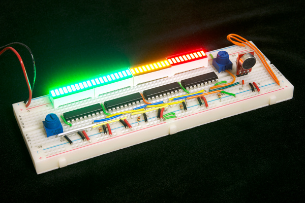
Dot/Bar Display Driver Hookup Guide
Introduction
The LM3914 and LM3916 are a two ICs in a series of monolithic, analog-controlled LED drivers. With these chips, all it takes is a single, analog signal to drive a string of 10+ LEDs, which can be configured into either bar mode (where all LEDs below a certain point turn on) or dot mode (with only a single LED on at a time). Hook them up properly, and you can create all sorts of nifty multi-LED displays, like an audio-visualizing VU meter.
These two ICs are similar in pin-out and interface. They differ in how they map an analog signal to output LED. The LM3914 uses a linear output scale while the LM3916 uses a more logarithmic VU (volume unit) scale, which makes it well-suited to audio applications.
In this tutorial we'll dig into the datasheet of these LED drivers to find out what makes them tick, and take a close look at the pinout of the 18-pin DIP chips. Finally, we'll show a pair of example circuits that show a simple hookup and a more advanced, cascaded hookup.
Required Materials
If you want to follow along with this tutorial, here are the components we used to make our driver circuits:
- IC: 1x LM3914 for the simple circuit, 2-4x LM3916 for the cascaded circuit.
- Display: 5mm LEDs and/or 2-4 Bar Graph LEDs
- A variety of resistors from the Resistor Kit
- Full-Size Breadboard
- Potentiometer (or any sensor that can produce an analog signal)
- Breadboard Jumper Wires
- Power Supply:
- 5V AC Adapter and Barrel Jack Adapter -or-
- Breadboard Power Supply (with male headers soldered in)
Suggested Reading
Working with these ICs is fairly simple -- no crazy microcontrollers or programming required! Here are a few basic electronics concepts you should be familiar with, before moving forward:
- Integrated Circuits (ICs)
- Analog vs. Digital
- Light-Emitting Diodes (LEDs)
- Resistors
- Voltage Dividers
- How to Use a Breadboard
