Dot/Bar Display Driver Hookup Guide
 jimblom
IC Overview
On this page we'll take a look at the pinout of the 18-pin LM3914/6. We'll also dig a little deeper to see what makes the ICs do what they do.
The Pinout
The DIP (through-hole, dual-inline package) version of this chip has 18 pins, and both a dot and notch to indicate polarity.
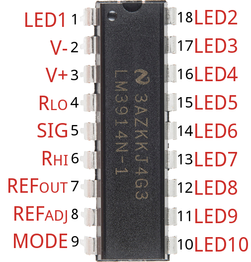
Over half of the pins are in charge of driving the LEDs. The remaining pins are used for power, reference voltages, and control of the IC. Here is an overview of the chip's pinout:
| Pin # | Pin Name | Pin Function | Pin # | Pin Name | Pin Function | |
|---|---|---|---|---|---|---|
| 1 | LED 1 | First (lowest value) LED | 18 | LED 2 | 2nd LED | |
| 2 | V− | Ground | 17 | LED 3 | 3rd LED | |
| 3 | V+ | Supply voltage (3-25V) | 16 | LED 4 | 4th LED | |
| 4 | RLO | Divider low voltage | 15 | LED 5 | 5th LED | |
| 5 | Signal In | Analog signal in | 14 | LED 6 | 6th LED | |
| 6 | RHI | Divider high voltage | 13 | LED 7 | 7th LED | |
| 7 | Ref Out | Reference output voltage | 12 | LED 8 | 8th LED | |
| 8 | Ref Adj | Voltage reference adjust | 11 | LED 9 | 9th LED | |
| 9 | Mode | Dot/Bar mode select | 10 | LED 10 | Last (higest analog input) LED |
That may seem a daunting list of pins and reference voltages to supply, but in reality it can be very simple. Many of those pins can either be tied to ground, VCC, or even left floating. Other pins may require a resistor or two to set constant current or voltage values.
LED Outputs
The LED outputs are all open-collectors, so they sink current. Connect the cathode of an LED to these pins and tie the other pin of the LED -- the anode -- to your voltage supply. There is no need for current limiting resistors, as the chip takes care of current regulation.
Mode Select
The Mode pin allows you to select between "bar" mode and "dot" mode. In bar mode, all LEDs sequentially turn on. So, if the signal voltage is near max, all LEDs should be on. In "dot" mode just a single LED is on at any time. Connect mode directly to the power source for bar mode, and leave it floating for dot mode.
| Mode | Mode Pin Setting |
|---|---|
| Bar Graph | Tied directly to V+ |
| Dot Display | Left floating (no connection) |
| Dot Display (cascaded drivers) | Mode pin of first driver connected to pin 1 of next. |
Setting the Analog Range with RHI and RLO
The RHI (pin 6) and RLO (pin 4) pins are used to map the sensing range of the LM3914/6. RHI sets the maximum voltage, and RLO sets the minimum voltage.
These two pins can be connected to any voltage as long as it's 1.5V below the supply voltage (V+), and greater than 0V.
Setting LED Current with Ref Out
The current drawn out of the Ref Out pin (pin 7) sets the current that flows through each LED, so this pin can be used to adjust the LED brightness.
If a resistor (RL) is connected from that pin to ground, the current flowing through each LED will be about equal to this equation:

So, for example, if you have a 1kΩ resistor connected from pin 7 to ground, the LED current should be around 12.5 mA.
If you have a more complex circuit connected to this pin, remember that the voltage between Ref Out and Ref Adj pin (pin 8) should be 1.25V. And the LED current is equal to 10 times the current coming out of Ref Out.
The Internals -- A Chain of Comparators
Note: It's not critical to understand how these chips work, but it is a neat study into the internals of an integrated circuit. Feel free to skip to the next page, if this looks a little too much like a Circuits I class.
The image below, from the LM3914/6 datasheet, provides an excellent overview of what's going on inside these chips:
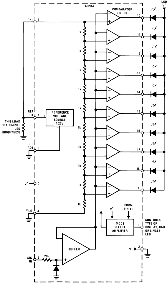
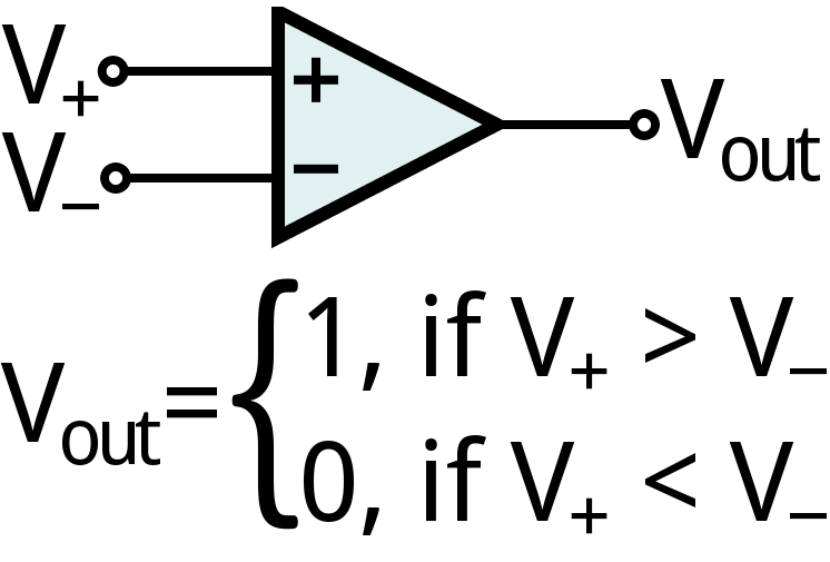
Each LED is controlled by the output of a comparator, which is a very simple op amp circuit. If the voltage going into the + (non-inverting) pin is greater than that going into − (inverting), the comparator outputs a 1 (high, or, in this case the pin "floats"). If the − pin voltage is greater than +, the output of the comparator is a 0 (pulled towards ground).
Inside the chip, the analog control signal from pin 5 is connected to each of the inverting (−) inputs on the comparators. The non-inverting (+) inputs of the comparators are connected to a string of 1kΩ resistors, which create larger-and-larger voltage dividers. The + voltage on the first comparator will be the divider input voltage (RHI − RLO), while the + voltage on the last comparator is 1/10th of that voltage.
To turn an LED on -- meaning the comparator's output is 0 -- the analog signal voltage must be greater than the divided input on a comparator. So a smaller signal voltage is required to turn on the first LED in comparison to any of the following.
Voltage and Current Ratings
The LM3914/6 ICs have a very wide supply voltage range: anywhere from 1.8V to 18V.
The voltage between the RHI and RLO pins can be anything between 0V (thought, that wouldn't be too useful) and 1.5V below the supply voltage. So, if you're powering the chip at 5V, it'll only be able to map voltages between 0V and 3.5V.
Also, keep in mind the current that might be flowing through the chip. Each LED can take anywhere between 7 and 13 mA, and to supply the chip you'll need an additional 2 to 9 mA.