Current Sensor Breakout (ACS723) Hookup Guide
 AGlass0fMilk, Eroc
 Calibration and Example Code
Note: This example assumes you are using the latest version of the Arduino IDE on your desktop. If this is your first time using Arduino, please review our tutorial on installing the Arduino IDE.
An example sketch for Arduino is included below to help you get started with the ACS723 Low Current Sensor. It will help you set the potentiometers and perform calculations to convert raw ADC readings into the actual current in mA. While parts are specific to the ACS723 Low Current Sensor, the main body of the sketch should work for the ACS723 Current Sensor as well.
To properly calibrate the ACS723 breakout board, you should first consider what type and range of currents you want to measure.
Choosing the Range
If you are going to be dealing mainly with DC, positive currents, you can adjust Vref to the lower end of its range. If you are trying to measure AC currents, you will want to keep Vref about in the middle at 2.5V. This lets your output swing equally in the positive and negative directions.
The gain setting will depend on the range of currents you want to measure. If you want to measure a current between 100mA and 500mA, you will want to set the gain so the sensitivity is something like 100mA/250mV (you will learn how to do this in the following steps).
Setting Vref
To get started, copy and upload the sketch below to your Arduino. You can also find the latest files in the GitHub repository.
language:c
/*  SparkFun ACS712 and ACS723 Demo
    Created by George Beckstein for SparkFun
    4/30/2017
    Updated by SFE
    6/14/2018

    Uses an Arduino to set up the ACS712 and ACS723 Current Sensors
    See the tutorial at: https://learn.sparkfun.com/tutorials/current-sensor-breakout-acs723-hookup-guide

    Parts you may need:
    - 100 Ohm, 1/2W or greater resistor OR two 220 Ohm 1/4 resistors in parallel
    - ACS712 Breakout with on-board amplifier or ACS723 Current Sensor (Low Current)

    Optional equipment:
    - Oscilloscope
    - Multimeter (or two)
    - A power supply with current limiting/constant current would be handy to calibrate the device without using resistors
*/

const int analogInPin = A0;

// Number of samples to average the reading over
// Change this to make the reading smoother... but beware of buffer overflows!
const int avgSamples = 10;

int sensorValue = 0;

float sensitivity = 100.0 / 500.0; //100mA per 500mV = 0.2
float Vref = 2500; // Output voltage with no current: ~ 2500mV or 2.5V

void setup() {
  // initialize serial communications at 9600 bps:
  Serial.begin(9600);
}

void loop() {
  // read the analog in value:
  for (int i = 0; i < avgSamples; i++)
  {
    sensorValue += analogRead(analogInPin);

    // wait 2 milliseconds before the next loop
    // for the analog-to-digital converter to settle
    // after the last reading:
    delay(2);

  }

  sensorValue = sensorValue / avgSamples;

  // The on-board ADC is 10-bits -> 2^10 = 1024 -> 5V / 1024 ~= 4.88mV
  // The voltage is in millivolts
  float voltage = 4.88 * sensorValue;

  // This will calculate the actual current (in mA)
  // Using the Vref and sensitivity settings you configure
  float current = (voltage - Vref) * sensitivity;

  // This is the raw sensor value, not very useful without some calculations
  //Serial.print(sensorValue);

  /*************************************************************************************
   * Step 1.)
   * Uncomment and run the following code to set up the baseline voltage
   * (the voltage with 0 current flowing through the device).
   * Make sure no current is flowing through the IP+ and IP- terminals during this part!
   *
   * The output units are in millivolts. Use the Arduino IDE's Tools->Serial Plotter
   * To see a plot of the output. Adjust the Vref potentiometer to set the reference
   * voltage. This allows the sensor to output positive and negative currents!
   *************************************************************************************/

  Serial.print(voltage);
  //Serial.print("mV");

  /*************************************************************************************
   * Step 2.)
   * Keep running the same code as above to set up the sensitivity
   * (how many millivolts are output per Amp of current.
   *
   * This time, use a known load current (measure this with a multimeter)
   * to give a constant output voltage. Adjust the sensitivity by turning the
   * gain potentiometer.
   *
   * The sensitivity will be (known current)/(Vreading - Vref).
   *************************************************************************************/

    /*************************************************************************************
   * Step 3.)
   * Comment out the code used for the last two parts and uncomment the following code.
   * When you have performed the calibration steps above, make sure to change the
   * global variables "sensitivity" and "Vref" to what you have set up.
   *
   * This next line of code will print out the calculated current from these parameters.
   * The output is in mA
   *************************************************************************************/

  //Serial.print(current);
  //Serial.print("mA");


  // -- DO NOT UNCOMMENT BELOW THIS LINE --
  Serial.print("\n");

  // Reset the sensor value for the next reading
  sensorValue = 0;
}
This sketch reads the voltage on pin A0 and prints it to the serial terminal. In later steps you will learn how to get actual current readings with this sketch.
To set up Vref, the sensor should have no current flowing through it! For this part, you only need to connect the ACS723's GND pin to Ground, VO pin to pin A0 on the SparkFun RedBoard (or equivalent), and 5V to the 5V pin on the RedBoard. If you have one available, it may be useful to also read the output voltage using a multimeter. See the Fritzing diagram below for more information:

If you aren't using a multimeter to set Vref, open up the Arduino IDE's serial plotter by clicking Tools->Serial Plotter. This will show the voltage reading from the Arduino in real time. The units are in millivolts.
Turn the Vref potentiometer clockwise to increase Vref and counter-clockwise to decrease. Make small adjustments, as the adjustment is very sensitive!
In the Serial Plotter, you should see something like this:
Tune Vref to about where you want it, for example 2500mV.
Setting Gain and Sensitivity
To set the gain, you need to pass a known current through the sensor and tune the gain pot to achieve the sensitivity your application needs.
For example, if you want to measure between 100mA and 500mA, you should shoot for a sensitivity of around 100mA/250mV. To do this, you can pass 100mA through the sensor, and adjust the gain pot until the output voltage is 250mV above your set Vref.
For those of you who have a benchtop power supply with a current limiter/constant current (CC) mode, getting this 100mA current is easy. In this case, you can simply connect the positive terminal of the power supply to the IP+ pin and the negative terminal of the power supply to the IP- pin. Make sure your current limit is set to something reasonable (NOT above 5A), and turn the power on. Adjust the output to a constant 100mA current for use in adjusting the gain.
If you don't have a power supply, all you need are some resistors (like in this nifty resistor kit, or these power resistors for more power dissipation). To make a fixed, known current, just use Ohm's Law!
If you want a 100mA current from a 5V source you need (5/0.1) = 50Ω
You should keep in mind how much power your resistors can handle though! If not, they'll end up a bit toasty... With 5V and 100mA, the power would be 500mW or 1/2W. The small resistors in the kit above can only handle 250mW or 1/4W at most. But, wait! A resourceful engineer knows you can still use the 1/4W resistors, you just need to split the power dissipation. By placing equal resistors in parallel, you can increase the maximum allowable power dissipation; each resistor just adds their power rating. IE: 1/4W resistor + 1/4W resistor = 1/2W capacity! Keep in mind that the equivalent resistance will be lower though.
500mW is still a lot of power for these 1/4W resistors, so I recommend using only 50mA to tune the gain, unless you have the power resistors linked to above.
To get 50mA from 5V, you need 100Ω. Using parallel resistances, you need double that, or around 220Ω. You may want to use your multimeter to make sure the current flowing through the circuit is indeed 50mA. The tolerances of resistors can alter this current. To measure current with your multimeter, make sure to connect it in series! To see a diagram of how to build the circuit for setting the gain, see the Fritzing diagram below:
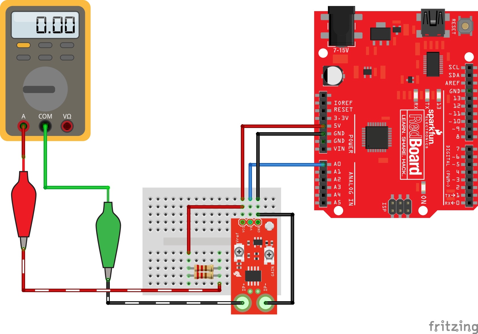
With a known, constant current flowing through the sensor, the gain can be adjusted. The same sketch can be used as last time. Open up the Serial Plotter again. To set the gain, disconnect one of the wires to break the current sensing circuit. When you reconnect it, see how much the output voltage increases. Subtract this from your Vref, to keep the voltage change (also known as delta). So, if you have 50mA flowing in the circuit, you want this change to be about 125mV for the 100mA/250mV sensitivity example. An example is shown below:
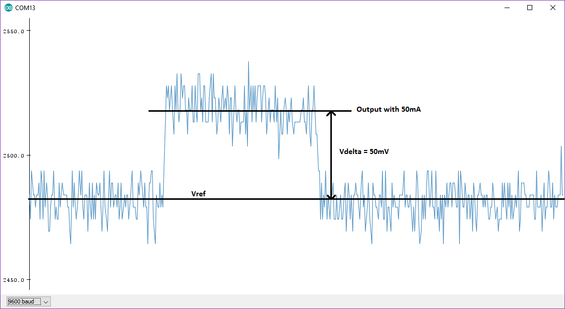
Adjust the change (Vdelta) to what you need it to be by tuning the gain potentiometer. As mentioned above, this affects the noise (spikiness) you see in the output:
Once you have Vref and the sensitivity settings selected, you can modify the code in the example sketch to print out your current readings in milliamps! Follow step 3 in the code comments to learn how to do this. Make sure to change the sensitivity and Vref variables to what you have set so the code can calculate the current properly.