CP2102 USB to Serial Converter Hook-Up Guide
Contributors:
 Toni_K
Toni_K 
Hardware Layout
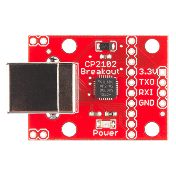
This breakout gives access to all 9 serial interface pins in easy-to-use 0.1" spaced footprints.
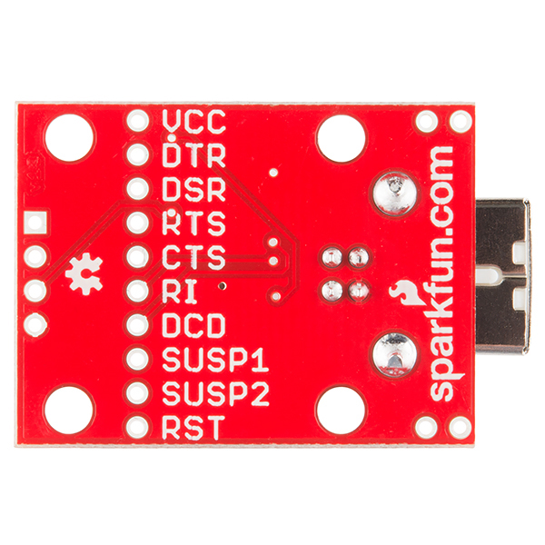
UART Interface
All of the serial interface pins are 5V tolerant.
- TX: Transmits from the board. A.K.A. Serial Output
- RX: Receives into the board. A.K.A. Serial Input
- DTR: Data Terminal Ready
- DSR: Data Set Ready
- RTS: Ready to Send
- CTS: Clear to Send
- RI: Ring Indicator
- DCD: Data Carrier Detect
These pins are labeled on the bottom of the board, as seen here.
Power Interface
There are two power pins available on the breakout board. VCC, which is connected directly to the USB 5V bus. This can show 4.6-5.2V depending on the regulation of the given USB port. If attached to a USB 2.0 port, then this pin can source up to 500mA, according to USB 2.0 specification.
A 3.3V pin is also available. This pin connects directly to the CP2102's internal regulator and can only source up to 100mA. This pin is broken out to the 4-pin basic serial connection at the board's edge.