CP2102 USB to Serial Converter Hook-Up Guide
 Toni_K
Overview
The CP2102 Breakout Board is a great tool for embedded systems that require a serial connection to a computer. The board attaches to the USB bus via a standard type B female connector, and appears as a standard COM port.
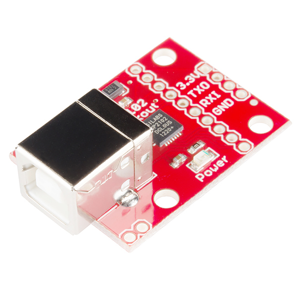
This IC doesn't require any external oscillator, has an on-board voltage regulator, and uses reprogrammable internal EEPROM for the device description. The full hardware UART has flow control for baud rates from 300bps to 921600bps. This breakout also allows you to connect the TX/RX pins of your favorite microcontroller or serial application to the RX/TX pins of the breakout, creating a simple serial cable replacement.
Required Materials
You will need the following materials to complete this hookup guide.
You will also need standard soldering tools to complete the circuit.
Suggested Reading
If you are not comfortable with the following concepts, you should review them before moving ahead with the CP2102 breaout board.
Hardware Layout
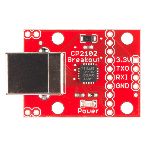
This breakout gives access to all 9 serial interface pins in easy-to-use 0.1" spaced footprints.
UART Interface
All of the serial interface pins are 5V tolerant.
- TX: Transmits from the board. A.K.A. Serial Output
- RX: Receives into the board. A.K.A. Serial Input
- DTR: Data Terminal Ready
- DSR: Data Set Ready
- RTS: Ready to Send
- CTS: Clear to Send
- RI: Ring Indicator
- DCD: Data Carrier Detect
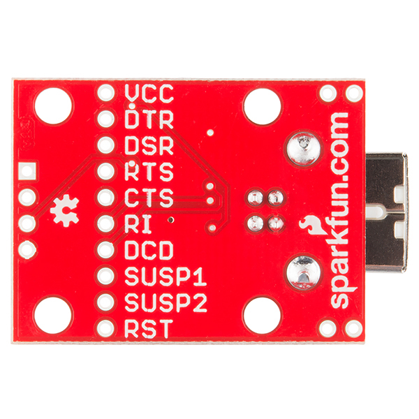
These pins are labeled on the bottom of the board, as seen here.
Power Interface
There are two power pins available on the breakout board. VCC, which is connected directly to the USB 5V bus. This can show 4.6-5.2V depending on the regulation of the given USB port. If attached to a USB 2.0 port, then this pin can source up to 500mA, according to USB 2.0 specification.
A 3.3V pin is also available. This pin connects directly to the CP2102's internal regulator and can only source up to 100mA. This pin is broken out to the 4-pin basic serial connection at the board's edge.
Driver Installation
You will need to download the appropriate drivers for your system. Currently, drivers are available for the following systems:
- Windows
- MacOS
- Linux
- Android
You can find the most up-to-date drivers for your system here, from Silicon Labs.
Installing Windows USB Drivers
Download and unzip the drivers. Plug in the breakout board to your computer via a USB A-to-B cable. Windows will attempt to install the driver software, but you may need to guide it the proper driver location of the unzipped files.
If for whatever reason you don't get the option to choose the driver location, you can manually install the drivers using the following steps.
Navigate to your Device Manager window. You should see something like the following:
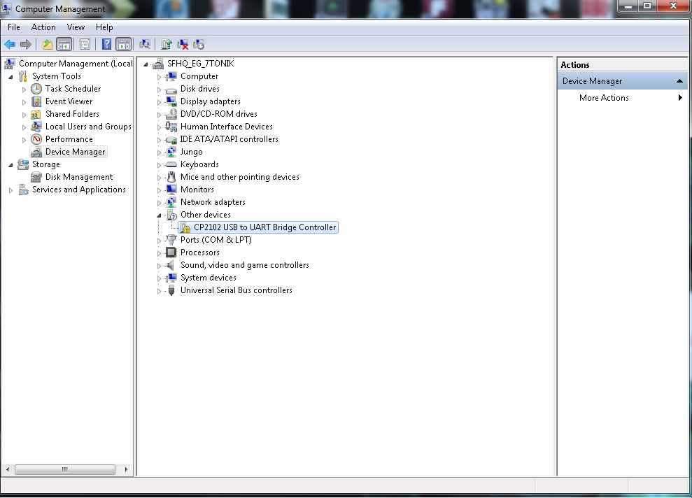
This means that the device is functioning, but Windows doesn't know how to communicate with the board. Right-click on the CP2102 device.
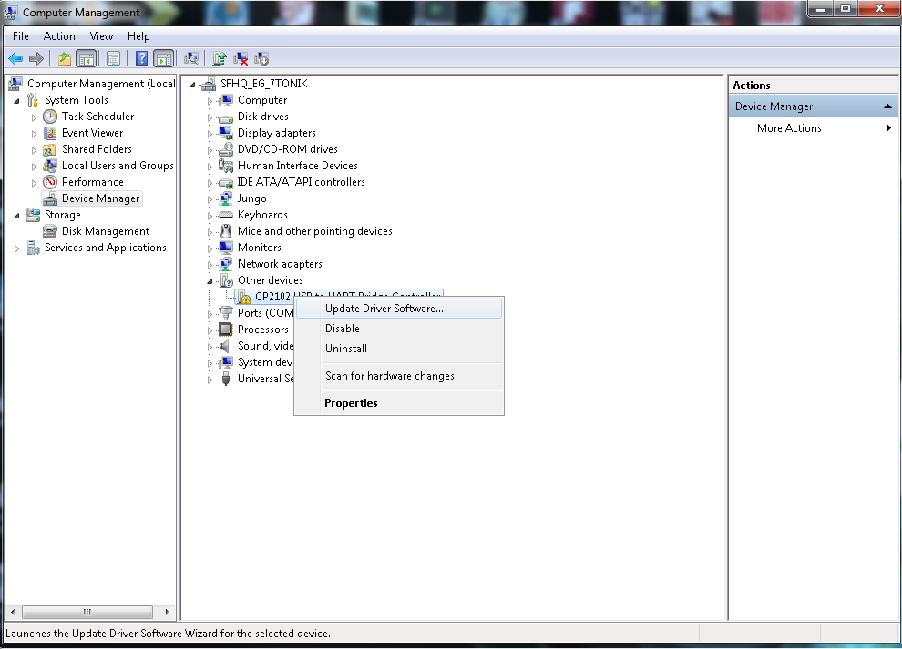
A drop-down menu will appear; select the "Update Drivers" option. You will then need to direct the computer to the location of the driver file you previously downloaded and unzipped.
Once the drivers have been properly installed, you should see the following in your Device Manager.
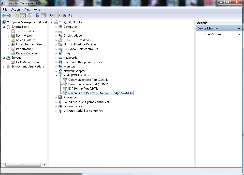
Note: The number associated with the CP2102 COM port will likely be different on your machine. This is not an error.
Once the breakout board is successfully installed, you can then connect to the board via your favorite terminal program.
Hardware Hook-Up
Soldering Connections
Solder header pins to the four pins labeled as 3.3V, TXO, RXI and GND on the edge of the board. You can also use bare wires for this, but for the ease of attaching and detaching the breakout board from differing systems, male to female jumper wires and header pins work well for this particular circuit.
Hooking It All Up
Make the following connections between your CP2102 breakout board and your 3.3V LCD screen.
**CP2102 Breakout → Serial Enabled LCD **
- 3.3V → VCC
- TXO → RX
- GND → GND
Operation
Once you have everything connected, plug in your CP2102 board over USB and open up your favorite terminal program. Make sure you have the correct settings for the port in your terminal at 9600bps, 8-N-1, and are connecting to the correct COM port.
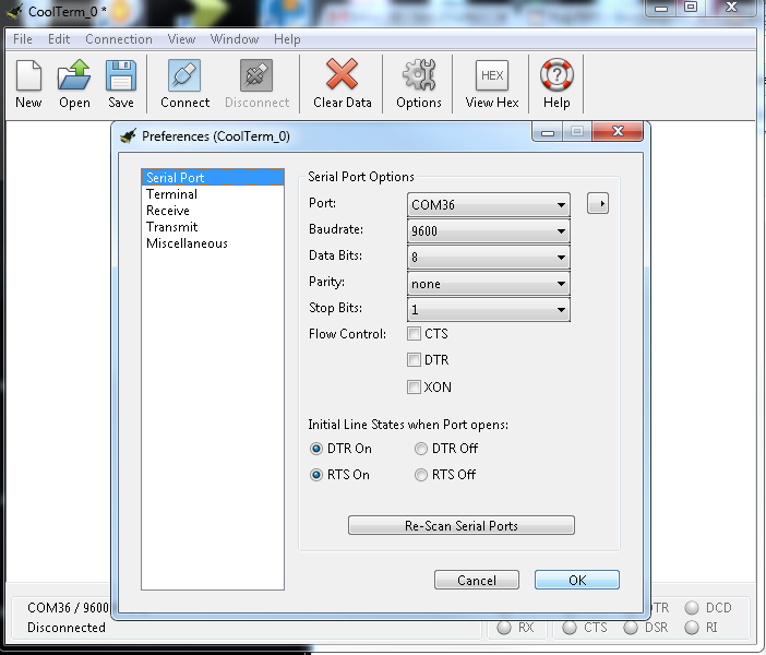
Once you have the proper settings for your COM port, start the connection. You should be able to type into your serial monitor on your screen, and have the values appear on the LCD.
Resources and Going Further
Going Further
Now that you've mastered the basics of working with the CP2102 breakout, you can begin integrating it into other projects. You could incorporate this with a single board computer, or create an easy-to-access sensor monitoring system. Check out some of the tutorials below to spark some other ideas.
We'd also love to get your feedback on this hookup guide and product in general. Let us know what you think in the comments!
Additional Resources
- CP2102 Datasheet-CP2102 Datasheet
- Pushing Data to Data.SparkFun.Com - Learn how to store your information in the cloud
- Using the BlueSMiRF - Learn how to make your project wireless