CP2102 USB to Serial Converter Hook-Up Guide
 Toni_K
Hardware Hook-Up
Soldering Connections
Solder header pins to the four pins labeled as 3.3V, TXO, RXI and GND on the edge of the board. You can also use bare wires for this, but for the ease of attaching and detaching the breakout board from differing systems, male to female jumper wires and header pins work well for this particular circuit.
Hooking It All Up
Make the following connections between your CP2102 breakout board and your 3.3V LCD screen.
**CP2102 Breakout → Serial Enabled LCD **
- 3.3V → VCC
- TXO → RX
- GND → GND
Operation
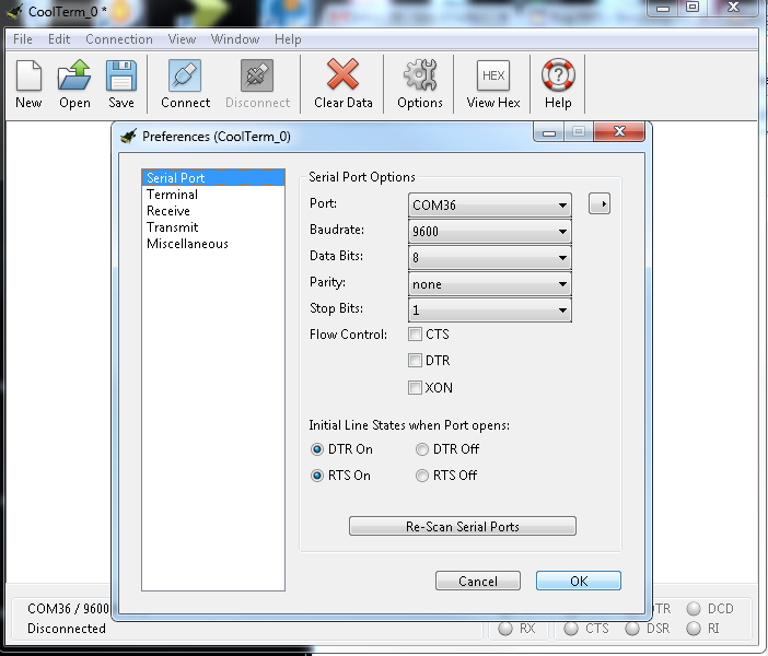
Once you have everything connected, plug in your CP2102 board over USB and open up your favorite terminal program. Make sure you have the correct settings for the port in your terminal at 9600bps, 8-N-1, and are connecting to the correct COM port.
Once you have the proper settings for your COM port, start the connection. You should be able to type into your serial monitor on your screen, and have the values appear on the LCD.