CCS811 Air Quality Breakout Hookup Guide
 MTaylor
Example: Additional Control Lines
The CCS811 has a couple extra control lines that are not part of the I2C bus, which can be utilized to improve the system. There's a pin to flag that data is ready, and a pin to make the sensor go to sleep.

To connect the interrupt line, connect it directly to an input pin. This is a 3.3V output from the sensor, so it's OK to drive the input logic of a 5V device from it. The example has nInt connected to pin 6.
To connect the wake stat line, use a voltage divider to divide the 5V coming from the Arduino down to something below 3.3V for the sensor. The example has nWake connected to pin 5 through a voltage divider made from two 4.7K resistors for a 2.5V output.
The example for these additional lines is called WakeAndInterrupt and is listed here:
language:c
/******************************************************************************
  WakeAndInterrupt.ino

  Marshall Taylor @ SparkFun Electronics

  April 4, 2017

  https://github.com/sparkfun/CCS811_Air_Quality_Breakout
  https://github.com/sparkfun/SparkFun_CCS811_Arduino_Library

  This example configures the nWAKE and nINT pins.
  The interrupt pin is configured to pull low when the data is
  ready to be collected.
  The wake pin is configured to enable the sensor during I2C communications

  Hardware Connections (Breakoutboard to Arduino):
  3.3V to 3.3V pin
  GND to GND pin
  SDA to A4
  SCL to A5
  NOT_INT to D6
  NOT_WAKE to D5 (For 5V arduinos, use resistor divider)
    D5---
         |
         R1 = 4.7K
         |
         --------NOT_WAKE
         |
         R2 = 4.7K
         |
        GND

  Resources:
  Uses Wire.h for i2c operation

  Development environment specifics:
  Arduino IDE 1.8.1

  This code is released under the [MIT License](http://opensource.org/licenses/MIT).

  Please review the LICENSE.md file included with this example. If you have any questions
  or concerns with licensing, please contact techsupport@sparkfun.com.

  Distributed as-is; no warranty is given.
******************************************************************************/
#include <SparkFunCCS811.h>

#define CCS811_ADDR 0x5B //Default I2C Address
//#define CCS811_ADDR 0x5A //Alternate I2C Address

#define PIN_NOT_WAKE 5
#define PIN_NOT_INT 6

CCS811 myCCS811(CCS811_ADDR);

//Global sensor object
//---------------------------------------------------------------
void setup()
{
  //Start the serial
  Serial.begin(9600);
  Serial.println();
  Serial.println("...");

  CCS811Core::status returnCode;

  //This begins the CCS811 sensor and prints error status of .begin()
  returnCode = myCCS811.begin();
  Serial.print("CCS811 begin exited with: ");
  printDriverError( returnCode );
  Serial.println();

  //This sets the mode to 60 second reads, and prints returned error status.
  returnCode = myCCS811.setDriveMode(2);
  Serial.print("Mode request exited with: ");
  printDriverError( returnCode );
  Serial.println();

  //Configure and enable the interrupt line,
  //then print error status
  pinMode(PIN_NOT_INT, INPUT_PULLUP);
  returnCode = myCCS811.enableInterrupts();
  Serial.print("Interrupt configuation exited with: ");
  printDriverError( returnCode );
  Serial.println();

  //Configure the wake line
  pinMode(PIN_NOT_WAKE, OUTPUT);
  digitalWrite(PIN_NOT_WAKE, 1); //Start asleep

}
//---------------------------------------------------------------
void loop()
{
  //Look for interrupt request from CCS811
  if (digitalRead(PIN_NOT_INT) == 0)
  {
    //Wake up the CCS811 logic engine
    digitalWrite(PIN_NOT_WAKE, 0);
    //Need to wait at least 50 us
    delay(1);
    //Interrupt signal caught, so cause the CCS811 to run its algorithm
    myCCS811.readAlgorithmResults(); //Calling this function updates the global tVOC and CO2 variables

    Serial.print("CO2[");
    Serial.print(myCCS811.getCO2());
    Serial.print("] tVOC[");
    Serial.print(myCCS811.getTVOC());
    Serial.print("] millis[");
    Serial.print(millis());
    Serial.print("]");
    Serial.println();

    //Now put the CCS811's logic engine to sleep
    digitalWrite(PIN_NOT_WAKE, 1);
    //Need to be asleep for at least 20 us
    delay(1);
  }
  delay(1); //cycle kinda fast
}


//printDriverError decodes the CCS811Core::status type and prints the
//type of error to the serial terminal.
//
//Save the return value of any function of type CCS811Core::status, then pass
//to this function to see what the output was.
void printDriverError( CCS811Core::status errorCode )
{
  switch ( errorCode )
  {
    case CCS811Core::SENSOR_SUCCESS:
      Serial.print("SUCCESS");
      break;
    case CCS811Core::SENSOR_ID_ERROR:
      Serial.print("ID_ERROR");
      break;
    case CCS811Core::SENSOR_I2C_ERROR:
      Serial.print("I2C_ERROR");
      break;
    case CCS811Core::SENSOR_INTERNAL_ERROR:
      Serial.print("INTERNAL_ERROR");
      break;
    case CCS811Core::SENSOR_GENERIC_ERROR:
      Serial.print("GENERIC_ERROR");
      break;
    default:
      Serial.print("Unspecified error.");
  }
}

//printSensorError gets, clears, then prints the errors
//saved within the error register.
void printSensorError()
{
  uint8_t error = myCCS811.getErrorRegister();

  if ( error == 0xFF ) //comm error
  {
    Serial.println("Failed to get ERROR_ID register.");
  }
  else
  {
    Serial.print("Error: ");
    if (error & 1 << 5) Serial.print("HeaterSupply");
    if (error & 1 << 4) Serial.print("HeaterFault");
    if (error & 1 << 3) Serial.print("MaxResistance");
    if (error & 1 << 2) Serial.print("MeasModeInvalid");
    if (error & 1 << 1) Serial.print("ReadRegInvalid");
    if (error & 1 << 0) Serial.print("MsgInvalid");
    Serial.println();
  }
}
Notice that this example doesn't poll dataAvailable() to check if data is ready; instead it reads the state of a digital input. When the input is low, data is ready in the sensor and readAlgorithmResults(), then .getCO2() and getTVOC() are used as normal.
The WAK pin can be used to control the logic engine on the CCS811 to save a bit of power. When the WAK pin is low (or disconnected), the I2C bus will respond to commands, but when the pin is high it will not. Tens of microseconds are required to wake or sleep, so in this example, commands are wrapped with a 1ms delay.
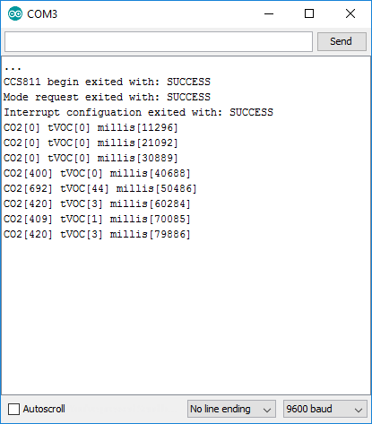
The terminal displays the calculation every 10 seconds. You can see that it take a few samples for the algorithm to spit out data, even at a slow rate of acquisition. Between the sampling, power is decreased as much as possible.
Summary:
To use WAK,
- Set up a digital output for the wake pin
- To communicate with a sleeping sensor,
- Set WAK low
- Wait 50us
- Do your communication
- Set WAK high
- Wait 20us
To use INT,
- Set up a digital input for the interrupt pin
- Enable interrupts with enableInterrupts()
- Look for a falling edge on the input to detect the availability of new data