Capacitive Touch Slider (CAP1203) Hookup Guide
Introduction
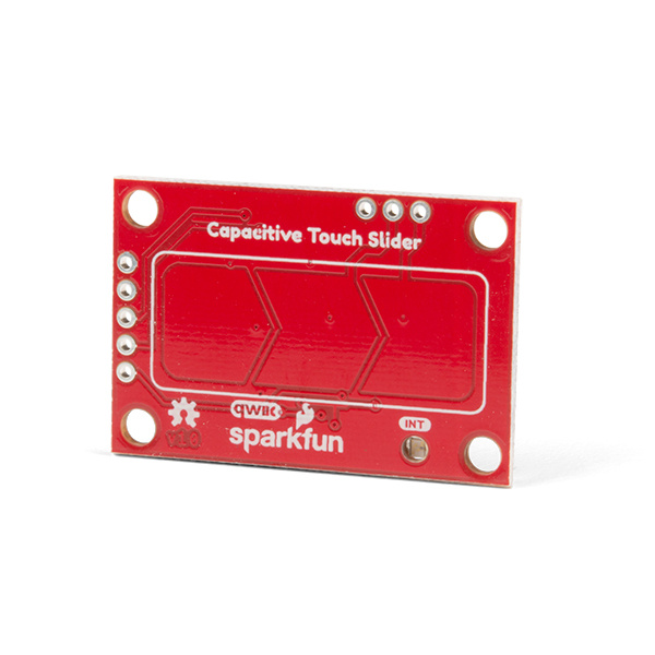
Do you want to replace a slider or a button on your art project or science experiment with a more interesting interface? The SparkFun Capacitive Touch Slider - CAP1203 (Qwiic) is a Qwiic and easy way to add capacitive touch to your next project. With the board's built in touch pads, you can immediately start playing with the touch capabilities as three unique touch inputs or as a slider. You can also enable a touch input to act as a power button, customize the sensitivity for your own touch pads, and play with the interrupt alert LED. Since the sensor supports I2C, we've added a Qwiic connector for easy integration into the Qwiic environment. We've also added breakout pins for the capacitive touch inputs, so you can connect to your own touch pads.
Required Materials
To follow along with the example code used in this tutorial, you will also need the following materials. You may not need everything though depending on what you have. Add it to your cart, read through the guide, and adjust the cart as necessary.


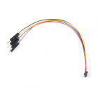
Qwiic Cable - 50mm
PRT-14426

If you need different sizes of Qwiic cables, we offer a kit that contains many sizes but we also carry them individually.


Qwiic Cable - 500mm
PRT-14429Suggested Reading
If you aren't familiar with the Qwiic system, we recommend reading here for an overview.
| Qwiic Connect System |
We would also recommend taking a look at the following tutorials if you aren't familiar with them.
Button and Switch Basics
Capacitors
I2C
How to Work with Jumper Pads and PCB Traces
RedBoard Qwiic Hookup Guide
Hardware Overview
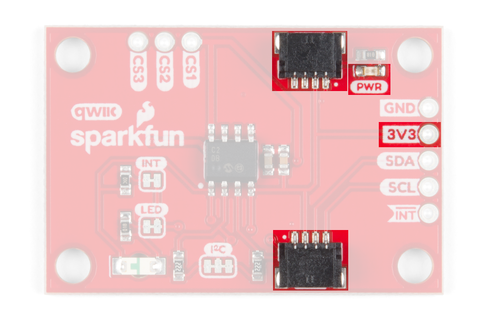
Power
You can provide 3.3V through the polarized Qwiic connectors on the board or through the 3V3 labeled pin on the through-hole header. The Qwiic system is meant to use 3.3V, so be sure you are NOT using another voltage when using the Qwiic system. When you have correctly powered the board, the red power LED will turn on.
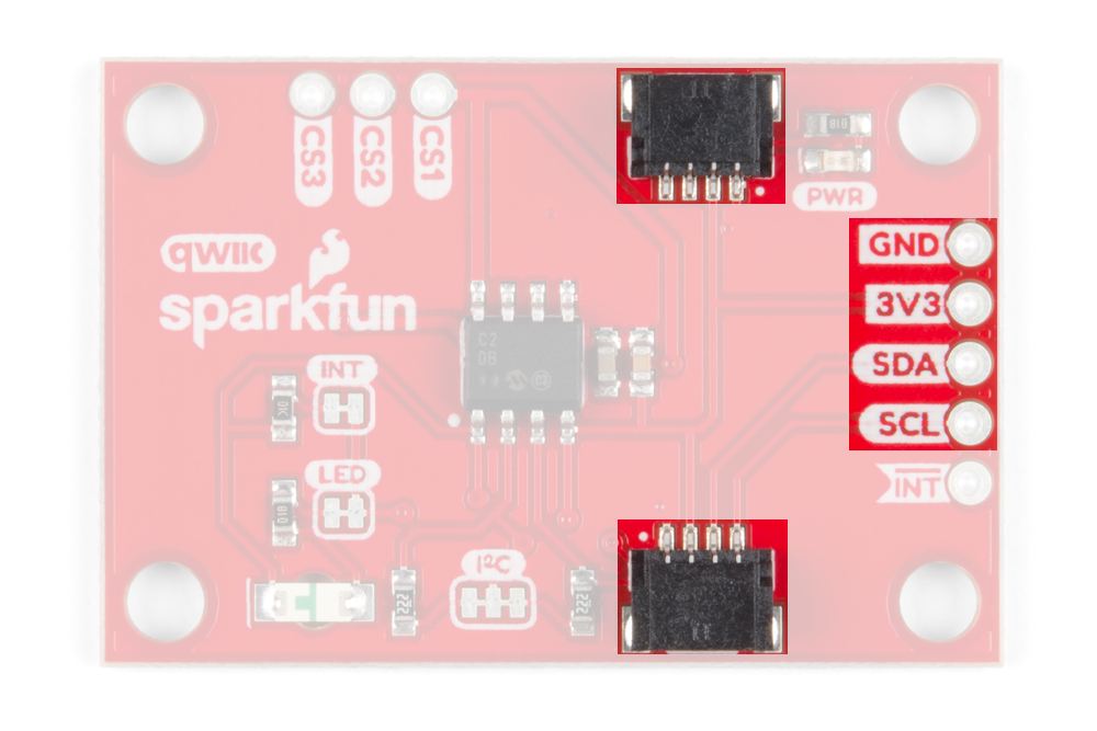
Qwiic Connectors or I2C Pins
There are two Qwiic connectors on the back of the board to easily connect the sensor to I2C. If you prefer the old school method of connecting to I2C, we've also included four breakout pins on the side of the board.
Interrupt Pin and LED
The interrupt pin is an active low output which is triggered each each time a sensor pad is touched. You can connect to this pin if you want to check when an interrupt occurs. On the front side of the board, the green LED in the bottom right corner also signals when an interrupt occurs.
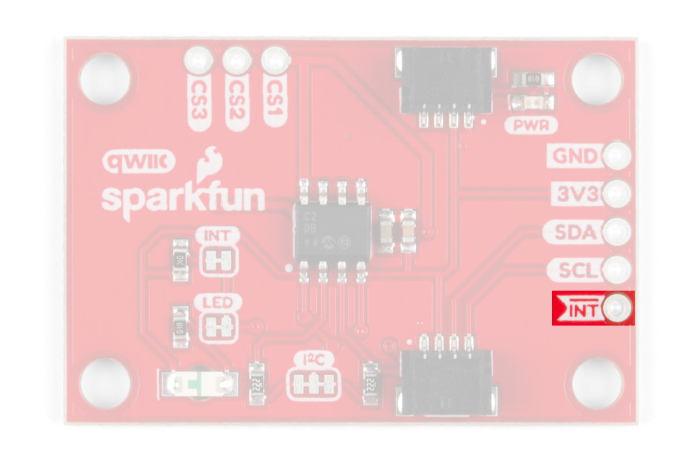

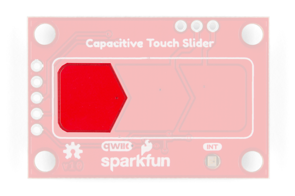
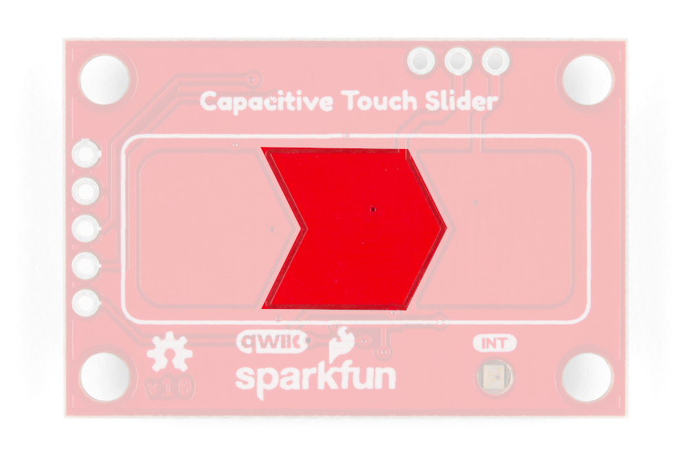
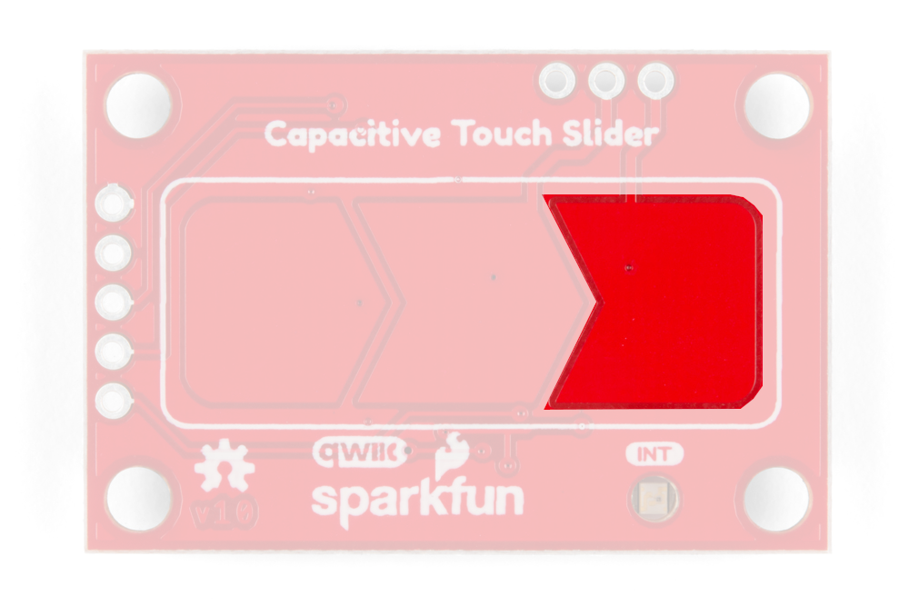
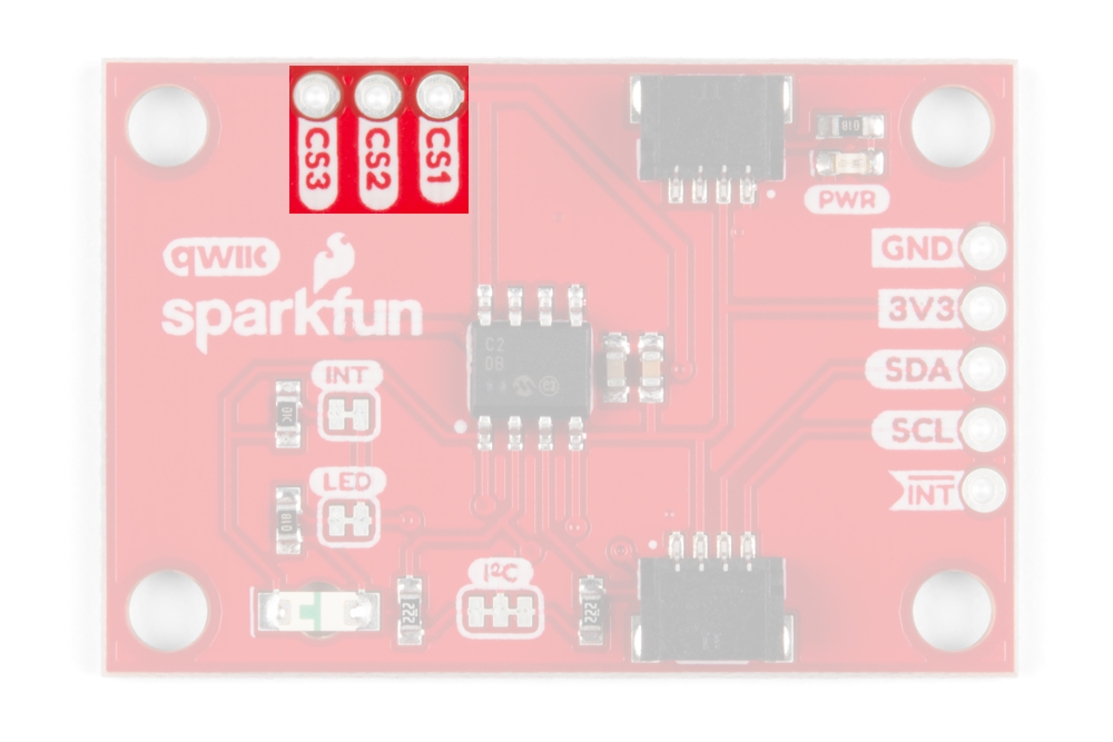
Capacitive Touch Pads and Pins
On the front of the board, there is an arrow shape which contains three separate capacitive touch pads. In order to know which pad is which, orient the board with the arrow pointing in the right direction. We will reference these capacitive touch pads as the left pad, the middle pad, and the right pad throughout the guide and in the code. We also broke out the capacitive touch sensor lines as plated through-holes on the top of the board. You can use these pins to connect to your own capacitive touch pads. The CS1 pin connects to the left pad, the CS2 pin connects to the middle pad, and the CS3 pin connects to the right pad.
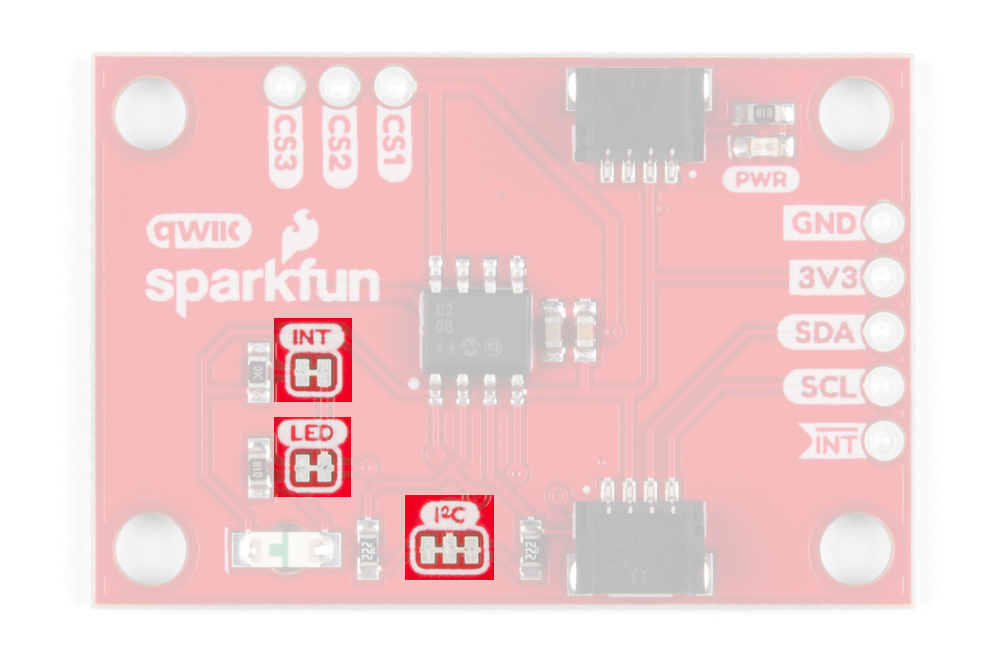
Jumpers
There are 3 jumper pads on the back of the board, each labeled with its function. First, on upper left side of the board, there is a two way jumper labeled INT that connects to a 10kΩ pull-up resistor on the interrupt data line. If you cut this jumper, it will disconnect the 10kkΩ pull-up resistor from the interrupt data line. Next, on the lower left side of the board, there is a two way jumper labeled LED that connects to the green interrupt LED. If you cut this jumper, it will disconnect the LED from the interrupt line, effectively disabling the green LED's functionality. Lastly, on the lower half of the board, there is a three way jumper labeled I²C that connects two 2.2kkΩ pull-up resistors to the I2C data lines. If you have multiple devices on your I2C data lines, then you may consider cutting this jumper. Not sure how to cut a jumper? Read here!
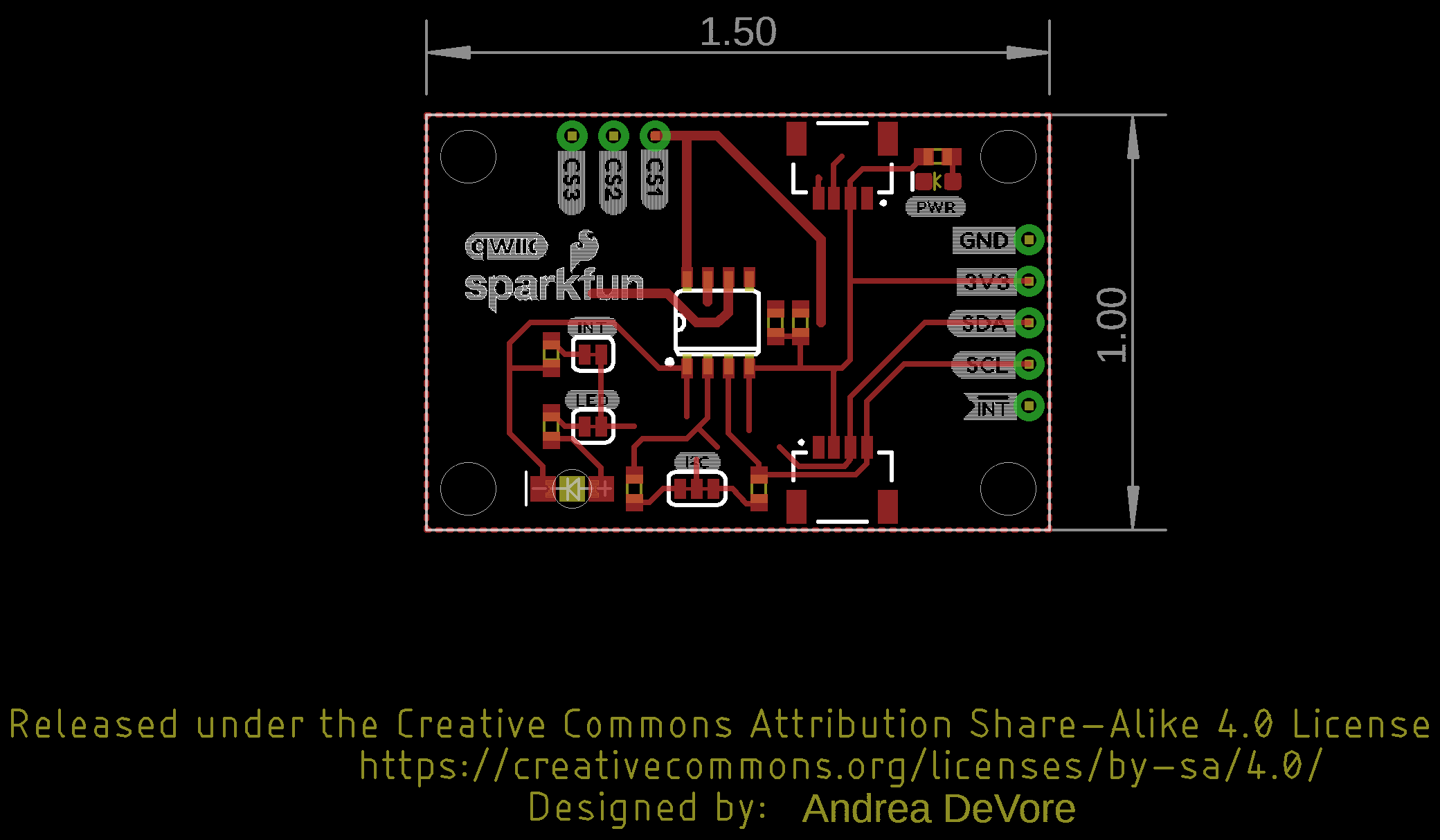
Board Measurements
The SparkFun Capacitive Touch measures 1 inch by 1.5 inches.
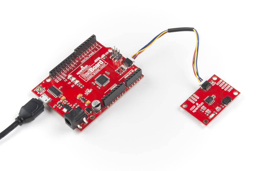
Hardware Assembly
With the Qwiic connector system, assembling the hardware is easy. For this tutorial, we use the SparkFun RedBoard Qwiic, an associated USB Cable, and a Qwiic cable. Plug your Qwiic cable between the RedBoard Qwiic and the Capacitive Touch Slider. Then, connect the microcontroller via the USB Cable to your computer. And...that's it! You're ready to start uploading code. Otherwise, if you're going to be soldering, then connect wires from the power, ground, and I2C data line breakout pins to the microcontroller of your choice. Using the CS1, CS2, and CS3 plated through-hole pins, you can also break out the capacitive touch lines to your own capacitive touch pads.
Arduino Library
We've provided a library to help you easily control and configure your Capacitive Touch Slider. You can download the library by searching 'SparkFun Qwiic Capacitive Touch Slider' in the Arduino library manager. Some of the features include reading when a pad is touched, detecting right and left swipes, enabling a power button, and setting the sensitivity for your own touch pads. You can also manually install the library by clicking the button below to get the library from it's GitHub repository. We have provided seven different example sketches to help you get started.
Library Functions
The Arduino library is commented and the functions should be self explanatory. However, below is a detailed list of the available library functions.
Initialization Settings: We use these to set-up and initialize the board.
.begin() - Initialize the sensor, returns true if correctly set-up
.isConnected() - Checks I2C connection, returns true if correctly connected
Sensitivity Settings:
These functions allow you to change the sensitivity settings for your touch pads. Note, the default sensitivity is set to SENSITIVITY_2X in the .begin() function for the SparkFun Capacitive Touch Slider board. We only recommend changing the sensitivity setting if you are breaking out your own touch pads.
.setSensitivity(sensitivity) - Sets the sensitivity multiplier for the touch pads
Possible sensitivity argument values:
SENSITIVITY_128X - Most sensitive
SENSITIVITY_64X
SENSITIVITY_32X
SENSITIVITY_16X
SENSITIVITY_8X
SENSITIVITY_4X
SENSITIVITY_2X
SENSITIVITY_1X - Least sensitive
.getSensitivity() - Returns the sensitivity multiplier for the current sensitivity settings, returns as an integer value
Power Button Settings: These functions allow you to enable or disable the power button on a specific pad. The power button requires a longer touch before registering a touch has been detected on the designated pad. Note, when the power button is enabled, the designated pad will only act as the power button.
.setPowerButtonPad(pad) - Sets a button to act as a power button, returns true if correctly set
Possible pad argument values:
PAD_LEFT - Left pad and CS1 breakout pin
PAD_MIDDLE - Middle pad and CS2 breakout pin
PAD_RIGHT - Right pad and CS3 breakout pin
.getPowerButtonPad() - Returns which pad is currently set to be the power button, returns as an integer value
Return values:
1 - Left pad and CS1 breakout pin
2 - Middle pad and CS2 breakout pin
3 - Right pad and CS3 breakout pin
.setPowerButtonTime(time) - Sets the power button touch time, returns true if correctly set
Possible time argument values:
PWR_TIME_280_MS
PWR_TIME_560_MS
PWR_TIME_1120_MS
PWR_TIME_2240_MS
.getPowerButtonTime() - Returns length of time (ms) power button must indicate a touch, returns as an integer value
.setPowerButtonEnabled() - Enables power button functionality
.setPowerButtonDisabled() - Disables power button functionality
isPowerButtonEnabled() - Returns true if power button functionality is currently enabled
Interrupt Settings:
These functions allow you to control if the interrupt pin is enabled. When enabled, the green interrupt LED will turn on when any pad detects a touch. Note, the interrupt is enabled as default in the .begin() function.
.setInterruptDisabled() - Disables interrupt pin
.setInterruptEnabled() - Enables interrupt pin
.isInterruptEnabled() - Returns true if interrupt pin is currently enabled
Check if a capacitive touch pad or breakout pin has been touched: These functions allow you to check when a capacitive touch pad or breakout pin has been touched.
.isLeftTouched() - Returns true if left pad or CS1 pin detects a touch
.isMiddleTouched() - Returns true if middle pad or CS2 pin detects a touch
.isRightTouched() - Returns true if right pad or CS3 pin detects a touch
.isTouched() - Returns true if any pad or breakout pin detects a touch
.isPowerButtonTouched() - Returns true if designated power button pad or pin held for alloted time
Check if a swipe has occured: The direction of the swipe is relative to the arrow on the board pointing in the right direction. For the pins, a right swipe is first CS1, then CS2, and finally CS3 and a left swipe is first CS3, then CS2, and finally CS1. Note, these functions pull most available resources. For best swipe recognition, we highly recommend not implementing other functionalities when using these two functions.
.isRightSwipePulled() - Returns true if board detects a right swipe
.isLeftSwipePulled() - Returns true if board detects a left swipe
Example Code
Please use the following links and the Internet for a better understanding of I2C and how it works in the Arduino IDE:
- A tutorial on I2C.
- An in-depth overview of the Wire (I2C) library.
Example 1: Basic Reading
The Example01_BasicReading.ino sketch works with the basic functionality of the Capacitive Touch Slider and streams which pad detects a touch. Open up the example to follow along. First, we include the CAP1203 library and initialize an instance of the sensor. Then, in the set-up function, we check to make sure the sensor is correctly connected. Now that the sensor is set-up, we can start checking which pads have been touched in the main loop using the .isLeftTouched(), .isMiddleTouched(), and .isRightTouched() functions. Once you have uploaded the code, you can open your serial terminal to see when a pad has been touched. Make sure the baud rate in your serial terminal is set to 9600 baud, otherwise you won't see the correct output.

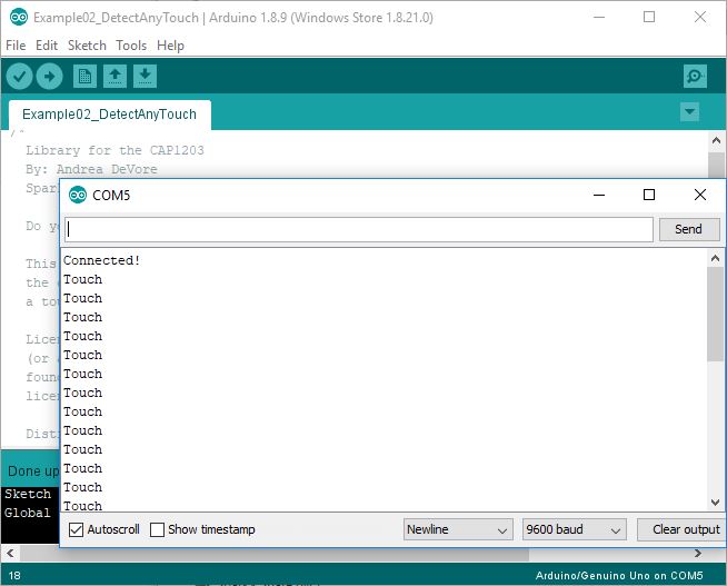
Example 2: Detect Any Touch
The setup for Example02_DetectAnyTouch.ino sketch is similar to Example 1, except it streams when any pad detects a touch using the .isTouched() function.
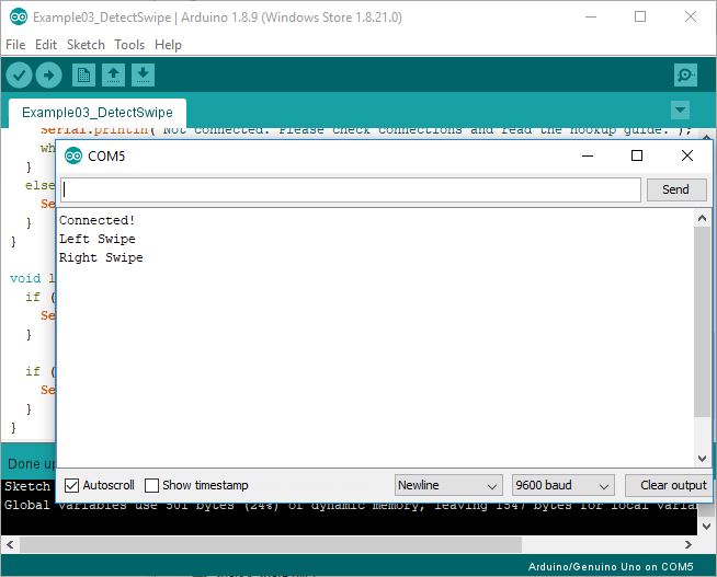
Example 3: Detect Swipe
The setup for Example03_DetectSwipe.ino sketch is similar to Example 1, except it streams when the board detects a swipe using the .isRightSwipePulled() and .isLeftSwipePulled() functions. The direction of the swipe is relative to the arrow on the board pointing in the right direction. Note, these functions pull most available resources. For best swipe recognition, we highly recommend not implementing other functionalities when using these two functions.
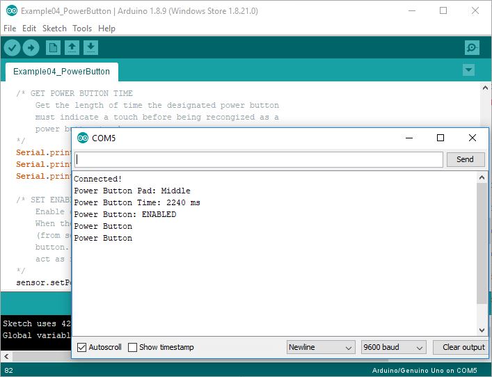
Example 4: Power Button
The Example04_PowerButton.ino sketch allows you enable or disable the power button feature on a specific pad. The power button requires a longer touch before registering a touch has been detected on the designated pad. Note, when the power button is enabled, the designated pad will only act as the power button. Configuring and enabling the power button feature requires some additional set-up.
In the sketch, we use the .setPowerButtonPad() and .setPowerButtonTime() functions to set which pad will act as the power button and the length of time the designated pad must indicate a touch. We also implement the .getPowerButtonPad() and .getPowerButtonTime() functions to check which pad and time we set with the previous two functions. Then, we enable the power button using the .setPowerButtonEnabled() function, and we check that the power button has been properly enabled using the .isPowerButtonEnabled() function. Finally, we check when the designated power button pad has been held for the allotted time using the .isPowerButtonTouched() function. The serial port prints Power Button when it registers a power button touch.
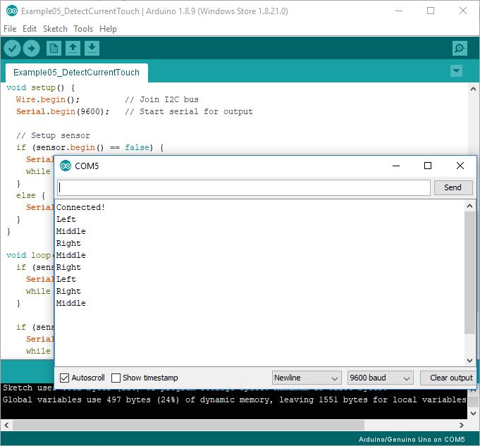
Example 5: Detect Current Touch
The Example05_DetectCurrentTouch.ino sketch uses the same functions and set-up as Example 1. However, Example 5 only notifies you about the current touch as opposed to a constant stream of touch data in Example 1. In order to do so, we added a while loop inside of each conditional statement. For example: while (sensor.isLeftTouched() == true).
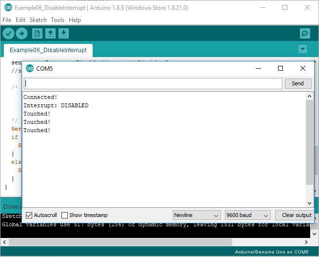
Example 6: Disable Interrupt
The Example06_DisableInterrupt.ino sketch allows you to programmatically adjust the interrupt settings. When disabled, the green interrupt LED will no longer turn on when a pad is touched. We use the .setInterruptDisabled() function to disable to interrupt and the .isInterruptEnabled() function to check the current interrupt settings. In the main loop, we then implement the .isTouched() function as in Example 2 to check that our board still registers a touch even though the interrupt LED no longer turns on.
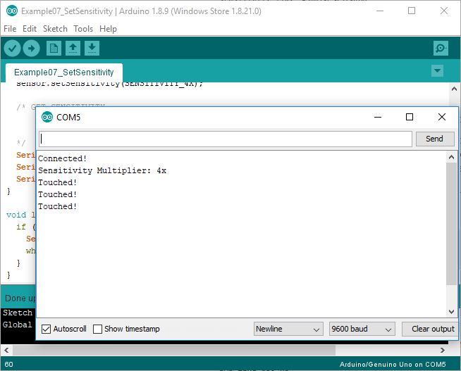
Example 7: Set Sensitivity
The Example07_SetSensitivity.ino sketch allows you to programmatically adjust the sensitivity settings for your capacitive touch pads. Note, we only recommend changing the sensitivity settings if you are breaking out your own touch pads. The current sensitivity settings are calibrated for the SparkFun Capacitive Touch Slider on board pads. In our example, we use the .setSensitivity() function to change the sensitivity and the .getSensitivity() to check our current sensitivity settings. In the main loop, we then implement the .isTouched() function as in Example 2 to check when the sensor has been touched with the new sensitivity settings.
Troubleshooting
Don't know if your board is working properly? To check that your board is properly hooked up, start by connecting your Capacitive Touch Slider and uploading the first example sketch to your microcontroller. Then, when you touch one of the pads, as demonstrated in the GIF, the green interrupt LED in the bottom right corner should turn on each time it senses a touch. (Note, if you have not yet uploaded code, the interrupt LED will turn on when you first connect to your microcontroller. The LED will turn off once you have uploaded the Example 1 code.) The red power LED on the back of the board, you can see its reflection on the table in the GIF, will also be on when the board is properly powered.
Resources and Going Further
Fore more on the Capacitive Touch Slider - CAP1203 (Qwiic) check out the links below.
- Schematic (PDF)
- Eagle Files (ZIP)
- Datasheet (PDF)
- Arduino Library
- GitHub Product Repo
- SFE Product Showcase
Need some inspiration for your next project? Check out some of these capacitive touch tutorials below!