Capacitive Touch Slider (CAP1203) Hookup Guide
Hardware Overview
Power
You can provide 3.3V through the polarized Qwiic connectors on the board or through the 3V3 labeled pin on the through-hole header. The Qwiic system is meant to use 3.3V, so be sure you are NOT using another voltage when using the Qwiic system. When you have correctly powered the board, the red power LED will turn on.
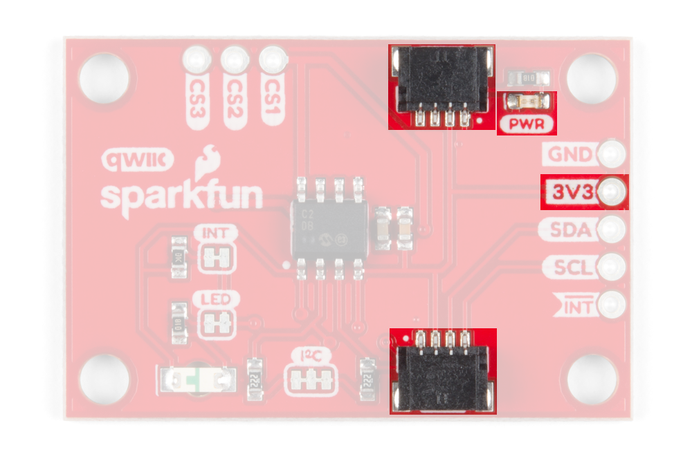
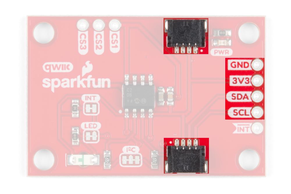
Qwiic Connectors or I2C Pins
There are two Qwiic connectors on the back of the board to easily connect the sensor to I2C. If you prefer the old school method of connecting to I2C, we've also included four breakout pins on the side of the board.
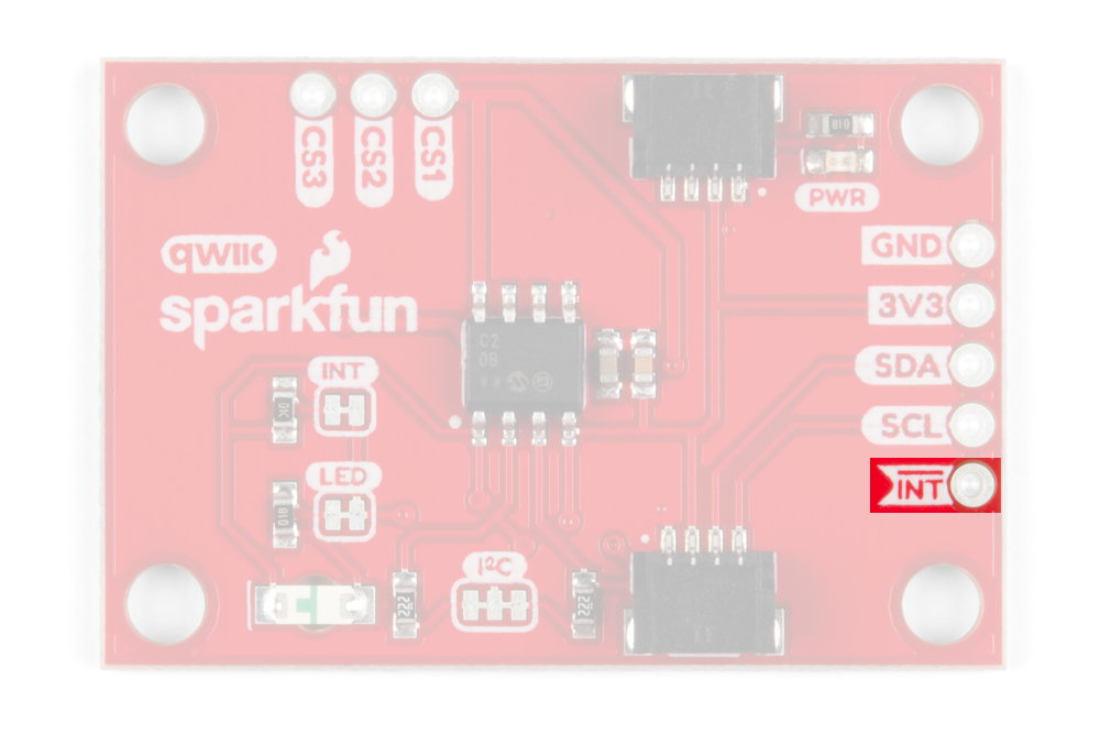
Interrupt Pin and LED
The interrupt pin is an active low output which is triggered each each time a sensor pad is touched. You can connect to this pin if you want to check when an interrupt occurs. On the front side of the board, the green LED in the bottom right corner also signals when an interrupt occurs.

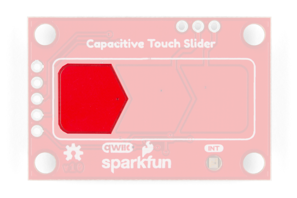
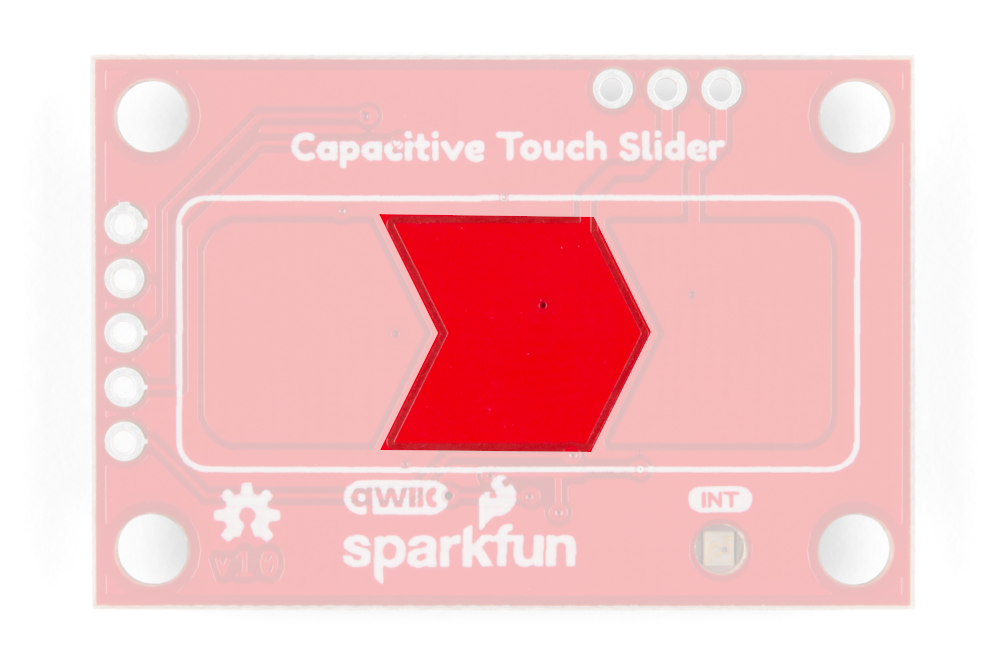
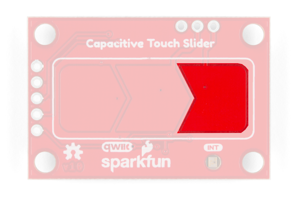
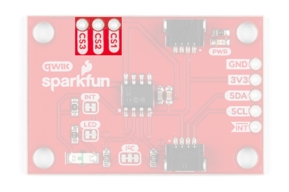
Capacitive Touch Pads and Pins
On the front of the board, there is an arrow shape which contains three separate capacitive touch pads. In order to know which pad is which, orient the board with the arrow pointing in the right direction. We will reference these capacitive touch pads as the left pad, the middle pad, and the right pad throughout the guide and in the code. We also broke out the capacitive touch sensor lines as plated through-holes on the top of the board. You can use these pins to connect to your own capacitive touch pads. The CS1 pin connects to the left pad, the CS2 pin connects to the middle pad, and the CS3 pin connects to the right pad.
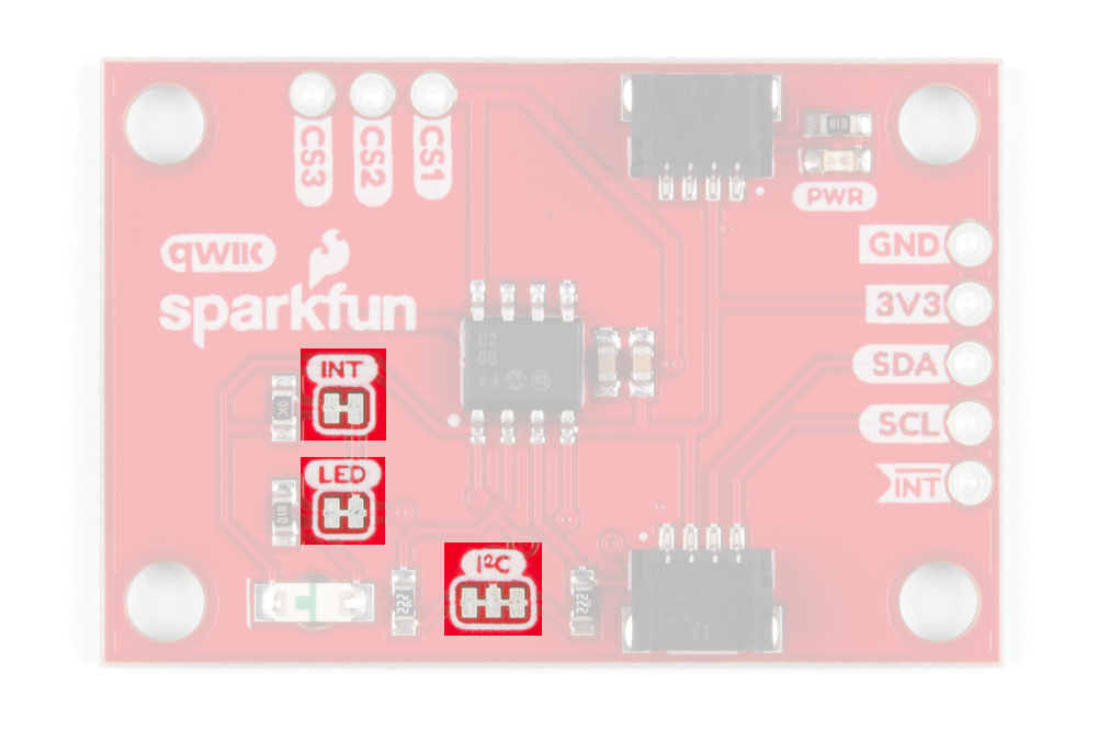
Jumpers
There are 3 jumper pads on the back of the board, each labeled with its function. First, on upper left side of the board, there is a two way jumper labeled INT that connects to a 10kΩ pull-up resistor on the interrupt data line. If you cut this jumper, it will disconnect the 10kkΩ pull-up resistor from the interrupt data line. Next, on the lower left side of the board, there is a two way jumper labeled LED that connects to the green interrupt LED. If you cut this jumper, it will disconnect the LED from the interrupt line, effectively disabling the green LED's functionality. Lastly, on the lower half of the board, there is a three way jumper labeled I²C that connects two 2.2kkΩ pull-up resistors to the I2C data lines. If you have multiple devices on your I2C data lines, then you may consider cutting this jumper. Not sure how to cut a jumper? Read here!
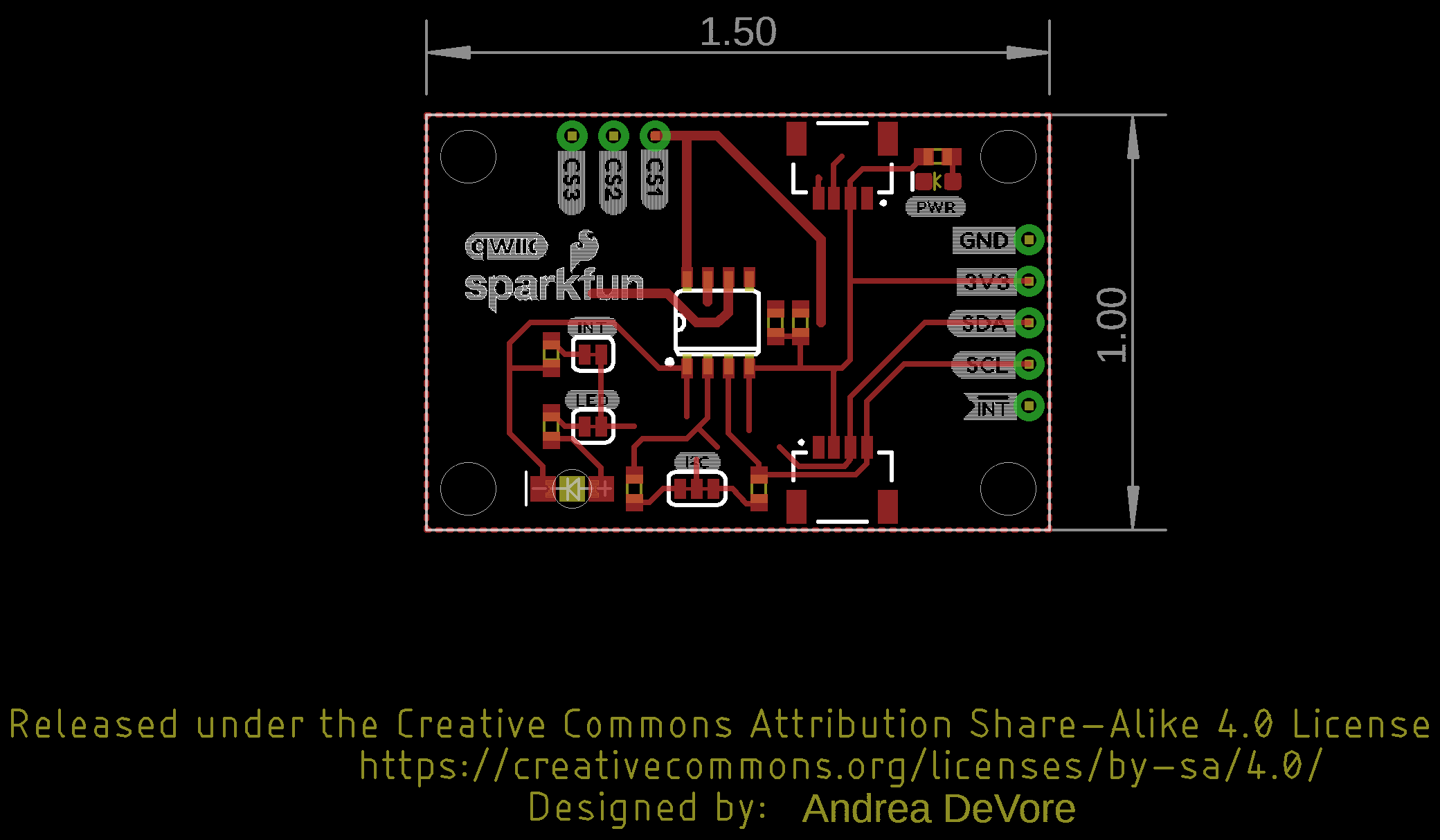
Board Measurements
The SparkFun Capacitive Touch measures 1 inch by 1.5 inches.