Bubble Display Hookup Guide
This Tutorial is Retired!
This tutorial covers concepts or technologies that are no longer current. It's still here for you to read and enjoy, but may not be as useful as our newest tutorials.
 Joel_E_B
Hardware Overview
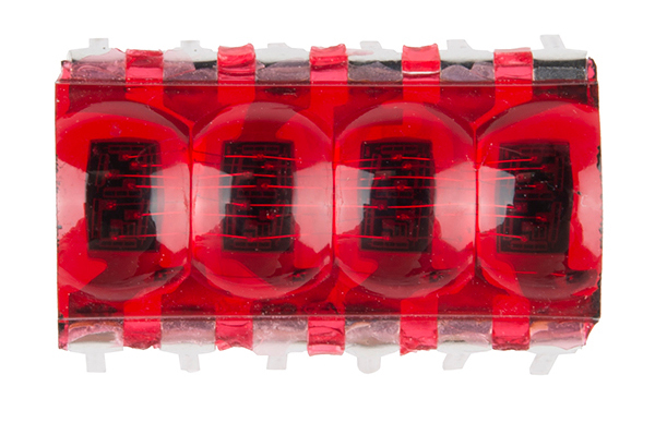
Let's briefly discuss the characteristics and functionality of the bubble display before we connect it to other hardware.
All the information found on this page and more can be found in the product's datasheet. Consult it, if you need more information.
Power
The bubble display is unique in that, unlike most ICs, these displays don't need a supply voltage. The bubble display is four, 7-segment displays packed into one package, and 7-segment displays are really just seven LEDs lined up in a particular pattern. In this case, the number '8' shape we're all familiar with. Thus, to turn on and off a particular part of the display, you send it a digital HIGH or LOW signal just like you would with a regular LED.
However, you may have noticed that there are more LEDs than there are pins on the IC. There are 32 segments total (counting the decimal points) and only 12 pins. What gives? The answer is that these displays use common-cathode LEDs, which means all the LEDs in a given segment share one ground pin. This is the same method used in RGB LEDs that allows you to control three different colored LEDs with only four pins. With these displays, there are eight pins for the anodes (+) (seven segments and one decimal point per digit) and four pins for the cathode (-) of each digit.
With that said, you still want to limit the amount of current flowing through the LEDs. If you are using a 5V microcontroller such as a SparkFun RedBoard, you'll need to add current limiting resistors to your circuit. Even if you're using a 3.3V micro, you should still add resistors, albeit much smaller values. The following tables from the datasheet give us the information we need to calculate the correct resistor value.

LED calculators, such as this one make it easy to figure out which value resistor to use. For example, if you're using a 5V source to control the segments, you'll want to have a 680 Ω resistor in line with each, assuming that each segment is operating under normal conditions. If you find that the display isn't as bright as you'd like it, you can always add a smaller value resistor. We've found that a 330Ω resistor works well on all four cathode pins.
Pinout
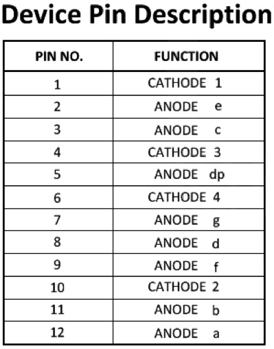
Now that we know how to properly provide power to the display, let's go over the segment configuration so we know which pins light up which segments. The pinout for the bubble display is as follows.
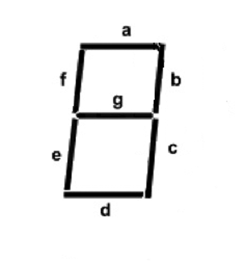
Next, take a look at the segment key.
Last, here is a diagram showing the numbering of the digits as they correspond to the pins labeled above.
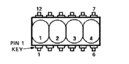
Building from what we discussed above, we can start to make sense of this. For example, let's say we wanted to turn on Segment_A on Digit_1. Looking at the table above we see that Segment_A (labeled Anode a) is pin 12. Looking at the same table, we can also see that the cathode for Digit_1 is pin 1. If you connect pin 1 to GND, and pin 12 to 3.3V or 5V (don't forget that resistor!), you should see the topmost segment on the leftmost digit light up. Yay LEDs! From here you can extrapolate how the rest works. If you wanted to light up Segment_A on both Digit_1 and Digit_4, you would simply add another connection to our first example from GND to pin 6 (cathode 4), and so on...
Lighting up individual segments is fun for about a minute, so let's move on and get this thing displaying some useful information.