Battery Babysitter Hookup Guide
 jimblom
Power-Path Management
One of the BQ24075's most unique features is dynamic power-path management (DPPM), which maintains a reliable output supply as long as either a battery or input supply (VIN/USB) are present.
The DPPM system can throttle charge current in order to maintain a reliable output supply. In the words of TI, DPPM "reduces the number of charge and discharge cycles on the battery," and it allows your project to "run with a defective or absent battery pack."
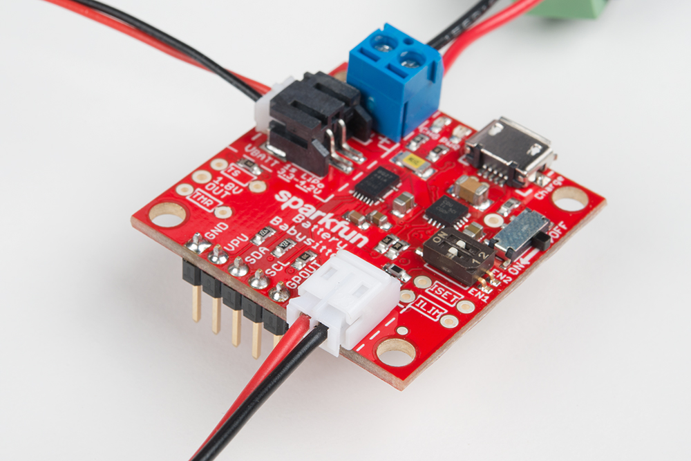
Footprints for a 0.1" header, 2-pin 3.5mm screw terminal and JST PTH connector are all connected to the power path management output.
Output Voltage Range
The output of the power-path management system is broken out to the "VOUT" pins, labeled "+" and "-". This supply output is active as long as either a battery or input supply are connected to the Battery Babysitter. (In the case of the battery-supply, the ON/OFF switch must be ON.) The voltage will swing between 3.0V and 5.5V, depending on the charge of your battery and the voltage/pressence of the input supply.
If the Battery Babysitter is powered by only a battery, the output voltage will usually be 50-100mV below the battery voltage. For example, a battery producing 3.75V might produce an output between 3.65 and 3.74V. A larger load, pulling more current, will create a bigger voltage drop.
If a 5V USB supply and battery are connected to the Babysitter, the output voltage will be somewhere between 3V and 5V, depending on the load, and charge percentage of the battery. If the battery is at, or near, full charge, the output could be as high as 5V. As the load increases, the voltage at the output supply will drop as low as 4.4V.
If your battery is charging, the output voltage will be around 4.3V, but may drop as low as 3.8V depending on the load.
TLDR
- If only a battery is present, the output should be about the battery voltage (minus a small drop).
- If battery and 5V USB are connected, and the battery is charging, the output will be 3.8 - 4.3V.
- If battery and 5V USB are connected, and the battery is fully charged, the output will be 4.5 - 5V.
Any load connected to VOUT should be able to handle a 3-5.5V input, but expect 3.6-5V assuming a healthy battery and USB supply. It's usually a good idea to regulate the output voltage of the Battery Babysitter to 3.3V, or find something that operates within the standard LiPo voltage range.
Power Path Operation Modes
The DPPM system is designed to protect a non-self-regulating charge supply by enforcing a limit on how much current that supply can source. Just as EN1 and EN2 are used to set charge current, they also control the input current limit:
| EN1 | EN2 | Power-Path Mode | Input Current Limit |
| 0 | 0 | Standby | USB suspend |
| 1 | 0 | DPPM | ILIM (1500 mA for ISET) |
| 0 | 1 | USB500 | 500 mA |
| 1 | 1 | USB100 | 100 mA (Default Charge Rate) |
These limits help guarantee that your input supply will not be tasked with sourcing more current than it's capable of.
If both VIN (USB or external) and a battery are connected and a load is pulling more than the set input current limit, the pair of supplies will supplement each other -- the input supply will source current to the set limit (100mA, 500mA, etc.), and the battery will take care of the rest.
Input Current-Limit Example
The DPPM's input current limits are designed to protect against over-loading a USB supply. If, for example, your Battery Babysitter is powering a project that is consistently drawing 1A and both a battery and USB supply are connected to the board, here is the current draw you might expect from the pair of supplies:
| Power-Path Mode | Current From Battery | Current From VIN (e.g. USB) |
|---|---|---|
| USB100 | 900 mA | 100 mA |
| USB500 | 500 mA | 500 mA |
| DPPM (set to 1.5A) | 0 mA | 1000 mA |
| Standby | 1000 mA | 0 mA |
Input Current Limit (ILIM)
An external resistor between the ILIM pin and ground is used to set the maximum input current in DPPM mode. This value is set by the following equation, where resistance is in ohms and current is in amps:
ILIM = 1550 / RILIM
The Battery Babysitter populates this pin with a 1.1kΩ resistor, which sets the input current limit in DPPM mode to about 1.4A.
To customize this resistance value, as with the other charger features, cut the ILIM jumper on the back of the board. Then, calculate your desired current/resistance values, and populate a PTH resistor into the available ILIM resistor footprint.