Battery Babysitter Hookup Guide
 jimblom
Battery Charging
To charge a LiPo battery with the Battery Babysitter, you can either connect a standard USB supply to the micro-B port
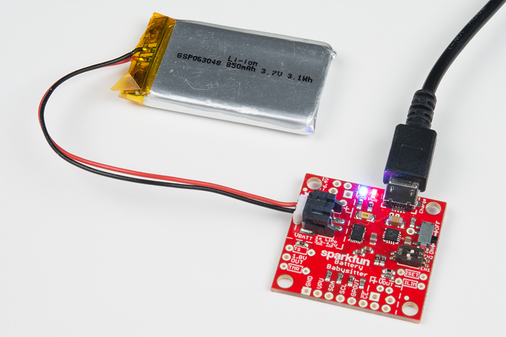
...or connect an external source to the VIN pins. These pins include a footprint for a 2-pin 3.5mm screw terminal jack as well as standard 0.1"-pitch headers.

For normal charging conditiions, the voltage coming into either USB or VIN should be within 4.35V and 6.4V. The BQ24075 does feature overvoltage protection, which means it can protect against input voltages up to 28V, but any voltage above about 6.6V will cause the charge controller chip to shut off and disable charging.
To enable charging the ON/OFF switch must be in the ON position. If the switch is set to the OFF position, charging is disabled (the CHG LED will still be illuminated – don't let it fool you!).
Charge LED Indicator
The blue CHG LED is connected to the BQ24075's CHG output. The LED will turn on when the battery is charging and off when charging is complete.
Setting the Charge Current
The 2-position DIP switch on the Battery Babysitter allows you to easily set the charge current to one of three constant-current values. The two switches set EN1 and EN2 of the BQ24075, which the "1" and "2" labels on the switch should match up to.
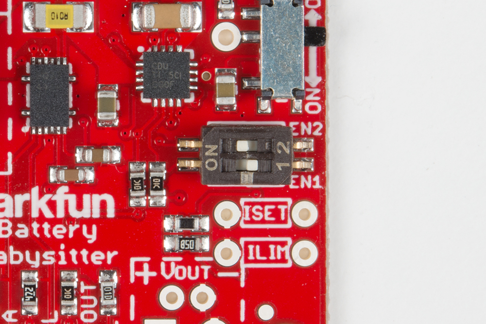
Consult the the table below for help setting your charge current. In the table, and throughout this tutorial, a 1 is equivalent to a switch in the "ON" position.
| EN1 | EN2 | Charge Rate |
| 0 | 0 | Suspend Mode (no charging) |
| 1 | 0 | Fast Charge (1500 mA with ISET) |
| 0 | 1 | 500 mA |
| 1 | 1 | 100 mA (Default Charge Rate) |
There is also a handy table on the back of the PCB, in case you forget which charge rate you currently have set.
If you're short on fingernails, a pair of tweezers or a small screwdriver may be helpful for toggling those tiny dip switch sliders.
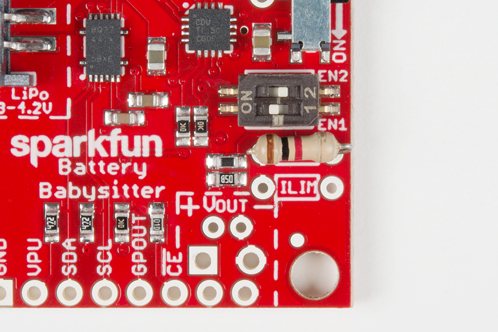
Customizing the Fast Charge Current (ISET)
Like many charge-controllers, the BQ24075 uses an external resistor to configure the charge current. The chip's ISET pin is broken out for this purpose. By default, the Battery Babysitter is set to deliver a 1.5A charge current in fast-charge mode when for the fast charge current ISET. But, by adding a custom resistor, you can drop that down to a more custom-fit charge rate.
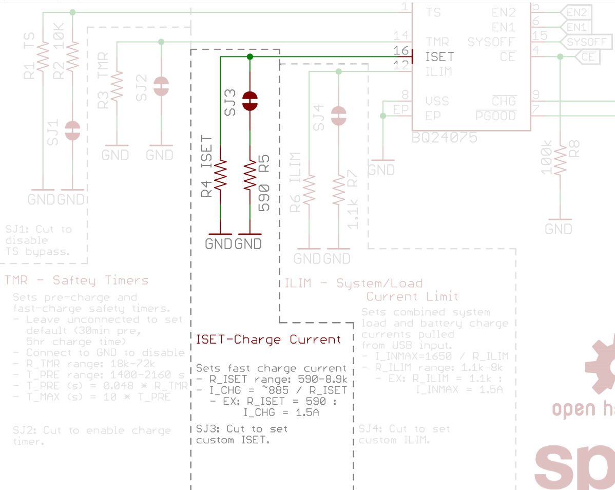
The equation below will determine the Battery Babysitter's fast-charge rate, based on the resistance between ISET and ground (RISET):
ICHARGE = 890 / RISET
- or -
RISET = 890 / ICHARGE
RISET and ICHARGE are in units of ohms (Ω) and amps (A), respectively.
ICHARGE can be set to anywhere between 100mA and 1500mA, which means RISET should fall somewhere between 590Ω and 8.9kΩ.
If you'd like to alter the fast-charge current, begin by cutting the ISET jumper on the back of the board.
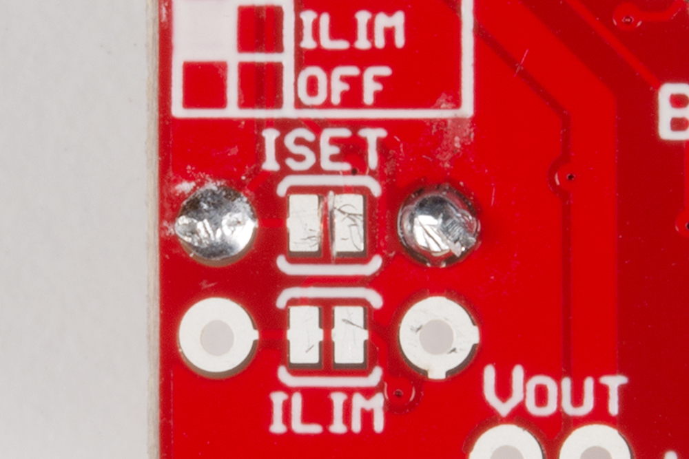
Then use the equation above to calculate an RISET value that will produce your desired charge current. If you want to set the charge current to 1A, for example, try to find a resistor around 890Ω. 1kΩ may be as close as you can get (with one resistor), which will set the charge current to 890mA.
Add the resistor across the unpopulated ISET pin, and solder the legs in.
Finally, make sure the DIP switch pins are set correctly (EN1 = 1, EN2 = 0).
Safety Timer (TMR)
The BQ24075 features a pair of charge timers that can may help prevent damage to a battery: a pre-charge timer and a max-charge timer.
Charge Phases
The BQ27045 varies charge current based on the voltage of the battery. There are three distinct phases of charging: pre-charge, fast-charge, and tapering.
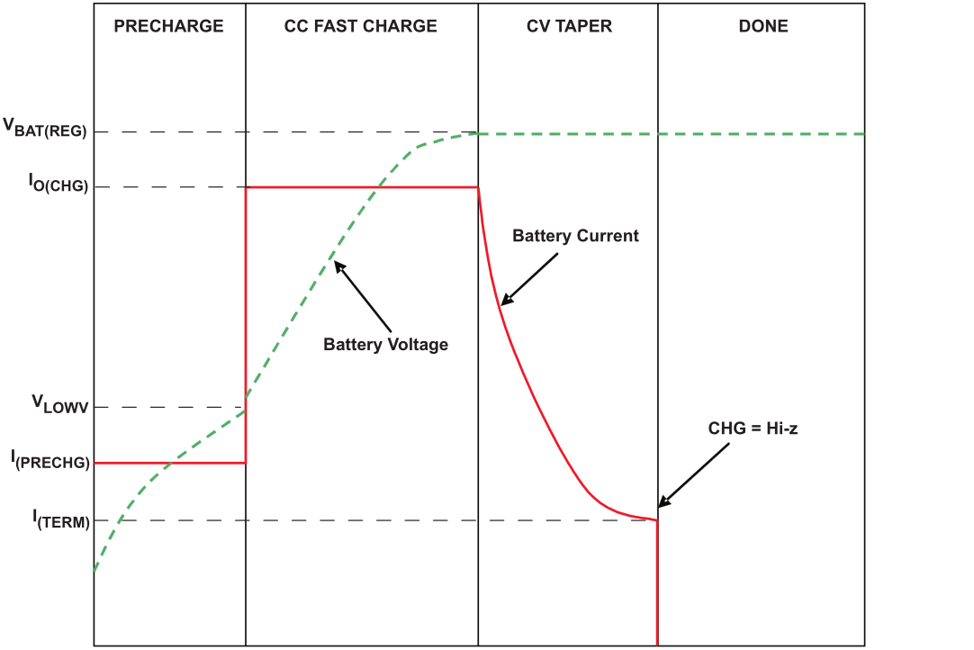
Typical charge cycle. (Figure 21 from the BQ27045 datasheet.)
The charger will be in pre-charge mode if the battery voltage is below about 3V. A battery this low on charge is in a fragile state and requires some delicate handling while it feeds on electrons to get back to a healthy level. In pre-charge mode, the charge current will be regulated to about 10% of the fast-charge current. For example, if the fast-charge current is set to 1.5A, the pre-charge current will be 150mA.
Fast-charge mode occurs while the battery voltage is between 3V and about 4.2V. During this state, the BQ27045 will charge the battery at constant current, determined by EN1 and EN2 (100mA, 500mA, or whatever the set fast-charge rate may be).
As the battery voltage nears 4.2V, the charge current will quickly taper off, as demonstrated in the graph above. In this state, the battery is held at a constant 4.2V.
The BQ24075's safety timers determine how long the BQ27045 can remain in either the pre-charge or fast-charge states, before giving up and shutting down. If a timer expires, the CHG LED will blink at 2Hz, and charging will be disabled. The timer can be cleared by toggling the CE pin from HIGH to LOW.
Setting the Saftey Timers
The length of the safety timers are determined by a resistor (or lack of resistor) connected to TMR. There are three timer-configuring options:
- Disable timer: Connect TMR to ground.
- Default timer: Leave TMR open.
- Custom timer: Connect a 18kΩ to 72kΩ resistor from TMR to ground to configure the timers.
The pre-charge and max-charge timers are set according to the following equations, based on a resistance from TMR to ground -- RTMR. (The calculated times are in seconds, resistance in ohms.)
tPRECHG = 0.048 × RTMR
tMAXCHG = 0.48 × RTMR
Resistor values between 18kΩ and 72kΩ can be added to set the maximum pre-charge time between 24-36 minutes, and the max-charge timer between 240 and 360 minutes.
As with customizing charge current, if you want to make a modification to the charge timers, you first need to cut the TMR jumper, then add an external resistor between TMR and ground.