Battery Babysitter Hookup Guide
 jimblom
 Introduction
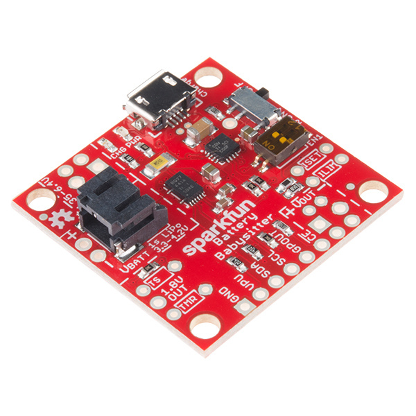
The SparkFun Battery Babysitter is an all-in-one single-cell lithium polymer (LiPo) battery manager. It's half battery-charger, half battery monitor, and it's all you'll ever need to keep your battery-powered project running safely and extensively.
The Battery Babysitter features a pair of Texas Instruments LiPo-management IC's: a BQ24075 battery charger and a BQ27441-G1A fuel gauge. The BQ24075 supports adjustable charge rates up to 1.5A, as well as USB-compliant 100mA and 500mA options. It also features power-path management, guaranteeing reliable power to your project.
The self-calibrating, I2C-based BQ27441-G1A measures your battery's voltage to estimate its charge percentage and remaining capacity. The chip is also hooked up to a current-sensing resistor, which allows it to measure current and power! It's a handy IC to have, especially if you ever need to keep an extra eye on your project's power draw.
Suggested Materials
You'll need a few components, accessories, and tools to get the Battery Babysitter up-and-running. The wishlist below includes all of the materials we use in this tutorial:
You can swap the RedBoard out for any Arduino-compatible development board. Regardless of whether it runs at 3.3V or 5V, 8MHz or 16MHz, any Arduino should work with the Battery Babysitter's fuel gauge IC.
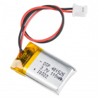
Likewise, just about any single-cell lithium-polymer battery should work as well. The Battery Babysitter's charger can be set as low as 100mA or as high as 1.5A, so if your batteries are best charged at 1C, look for LiPo's with capacities ranging from 100mAh to 1500mAh.


Lithium Ion Battery - 1Ah
PRT-13813Finally, you'll need a 5V supply to charge the battery, or just connect a USB cable into the on-board USB connector.
Suggested Reading
If you want to read up on some of the theories and concepts that the Battery Babysitter builds upon, check out some of these tutorials before continuing on:
Battery Technologies
Electric Power
I2C
What is a Battery?
Hardware Overview
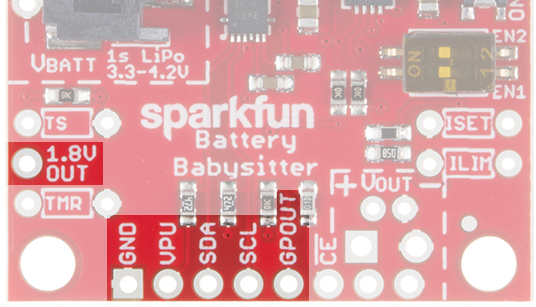
For quick reference, here is an annotated diagram of the Battery Babysitter's most prominent features, connectors, and control circuitry:
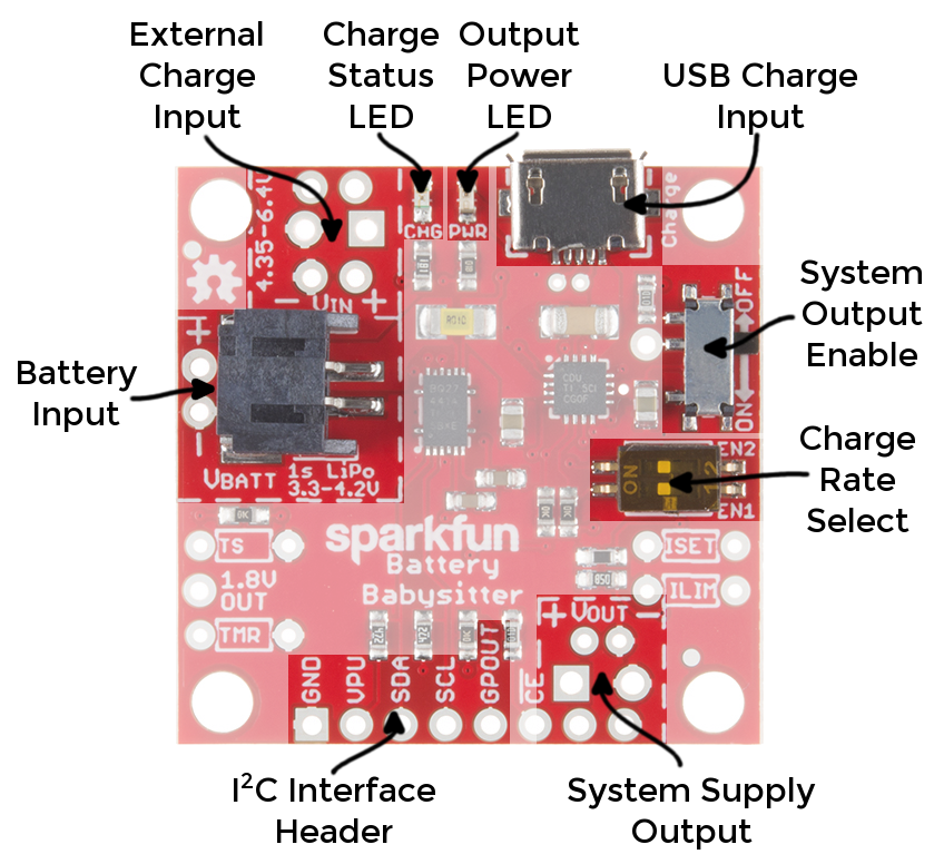
Below is a quick summary of the most significant components of the board. We'll go more in-depth on charging, powering, and gauging in the sections that follow.
Charge Input(s)
As a primary source for battery-charging, the Battery Babysitter provides a micro-B USB port. This USB connector is only used to charge the battery -- it will not show up as a USB device or pass any data through the port. (D+ and D- connectors are broken out to test points, though, if you want to change that.)
Alternatively, the External Charge Input port can be connected to any power supply between 4.35 and 6.4V. Keep in mind that the supply may be asked to source upwards of 1.5A, if the charge rate is set that high.
For more information on these two supply inputs, refer to the Battery Charging section of this guide.
Output Power and I2C Interface Headers
On the opposite side of the board sits the end goal of the Battery Babysitter: the voltage supply output. The voltage of this output supply will fall somewhere between 3V and 5.5V, depending on the state of your battery and/or presence of a charge supply. You can connect the rest of your system up to this supply output. For more information on the supply output header, refer to the Power-Path Management section of this guide.
Adjacent to that supply output is the BQ27441-G1A LiPo fuel gauge's I2C interface. In addition to the standard power and SDA/SCL pins, this header also includes a programmable interrupt output: GPOUT. For more on these pins, and the BQ27441's I2C interface, check out the LiPo Fuel Gague section.
System Output Enable -- ON/OFF Switch
The Battery Babysitter's ON/OFF switch toggles the "SYSOFF" pin of the BQ24075. It allows you to disconnect the battery from the system output -- effectively controlling power to a load when the Babysitter is in battery-powered operation.
There are some "gotcha's" to look out for with this switch:
- To enable charging, the switch must be in the ON position. Battery charging will be disabled if the switch is off.
- If a charge supply is connected -- whether it's USB or external -- the system output voltage will be enabled, regardless of the state of the switch.
Battery Charging
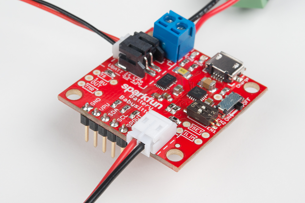
To charge a LiPo battery with the Battery Babysitter, you can either connect a standard USB supply to the micro-B port
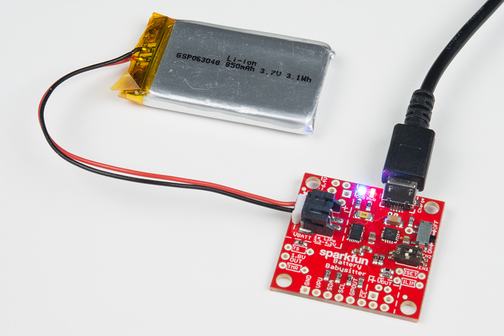
...or connect an external source to the VIN pins. These pins include a footprint for a 2-pin 3.5mm screw terminal jack as well as standard 0.1"-pitch headers.

For normal charging conditiions, the voltage coming into either USB or VIN should be within 4.35V and 6.4V. The BQ24075 does feature overvoltage protection, which means it can protect against input voltages up to 28V, but any voltage above about 6.6V will cause the charge controller chip to shut off and disable charging.
To enable charging the ON/OFF switch must be in the ON position. If the switch is set to the OFF position, charging is disabled (the CHG LED will still be illuminated – don't let it fool you!).
Charge LED Indicator
The blue CHG LED is connected to the BQ24075's CHG output. The LED will turn on when the battery is charging and off when charging is complete.
Setting the Charge Current
The 2-position DIP switch on the Battery Babysitter allows you to easily set the charge current to one of three constant-current values. The two switches set EN1 and EN2 of the BQ24075, which the "1" and "2" labels on the switch should match up to.
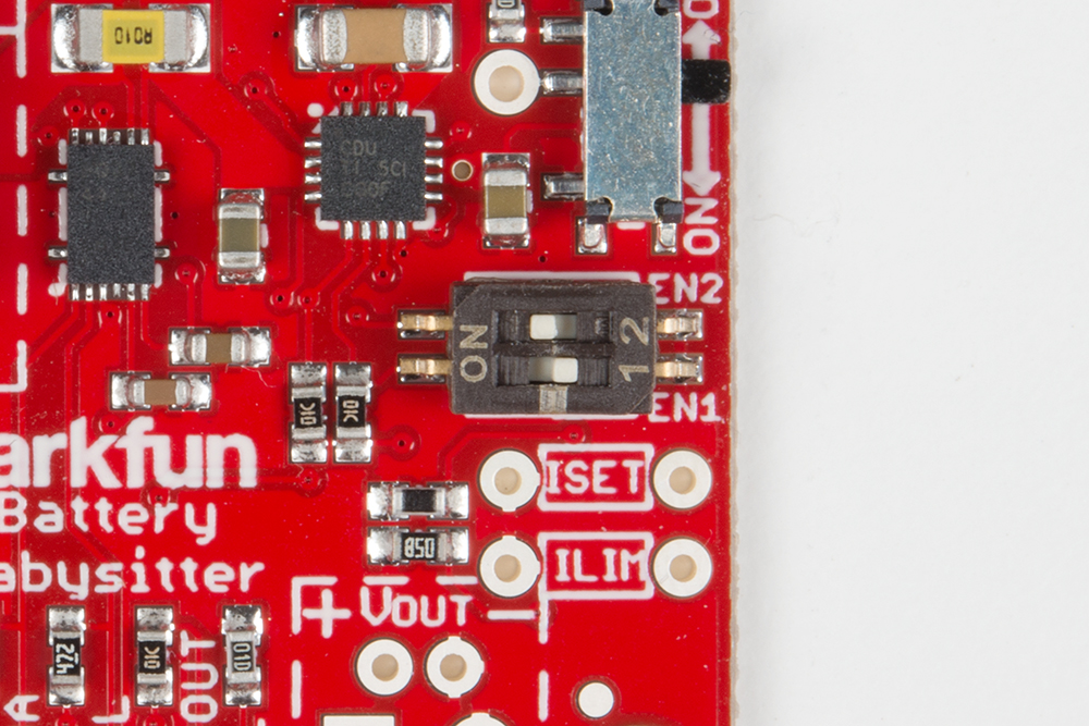
Consult the the table below for help setting your charge current. In the table, and throughout this tutorial, a 1 is equivalent to a switch in the "ON" position.
| EN1 | EN2 | Charge Rate |
| 0 | 0 | Suspend Mode (no charging) |
| 1 | 0 | Fast Charge (1500 mA with ISET) |
| 0 | 1 | 500 mA |
| 1 | 1 | 100 mA (Default Charge Rate) |
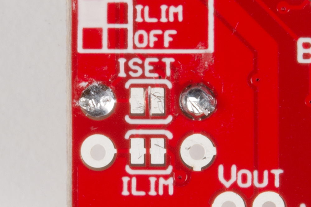
There is also a handy table on the back of the PCB, in case you forget which charge rate you currently have set.
If you're short on fingernails, a pair of tweezers or a small screwdriver may be helpful for toggling those tiny dip switch sliders.
Customizing the Fast Charge Current (ISET)
Like many charge-controllers, the BQ24075 uses an external resistor to configure the charge current. The chip's ISET pin is broken out for this purpose. By default, the Battery Babysitter is set to deliver a 1.5A charge current in fast-charge mode when for the fast charge current ISET. But, by adding a custom resistor, you can drop that down to a more custom-fit charge rate.
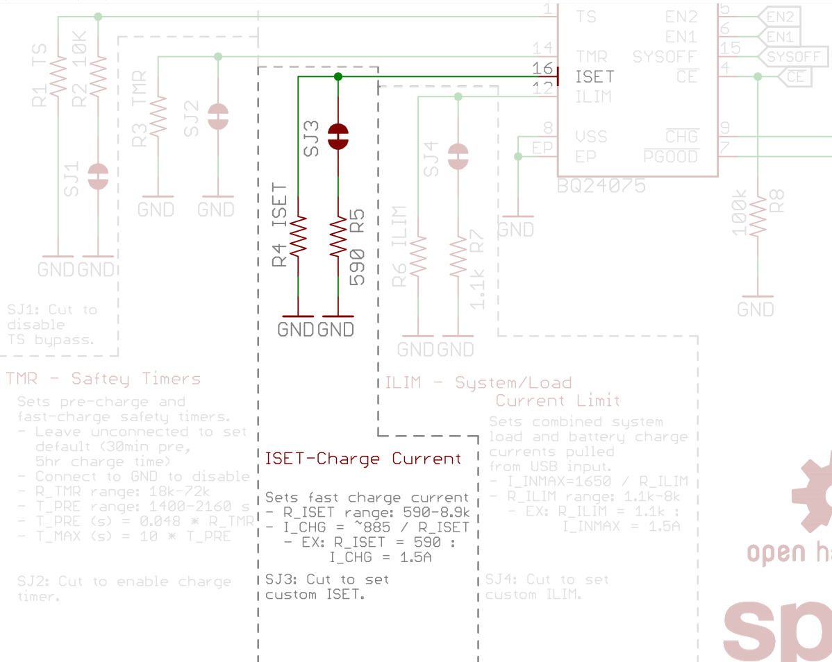
The equation below will determine the Battery Babysitter's fast-charge rate, based on the resistance between ISET and ground (RISET):
ICHARGE = 890 / RISET
- or -
RISET = 890 / ICHARGE
RISET and ICHARGE are in units of ohms (Ω) and amps (A), respectively.
ICHARGE can be set to anywhere between 100mA and 1500mA, which means RISET should fall somewhere between 590Ω and 8.9kΩ.
If you'd like to alter the fast-charge current, begin by cutting the ISET jumper on the back of the board.
Then use the equation above to calculate an RISET value that will produce your desired charge current. If you want to set the charge current to 1A, for example, try to find a resistor around 890Ω. 1kΩ may be as close as you can get (with one resistor), which will set the charge current to 890mA.
Add the resistor across the unpopulated ISET pin, and solder the legs in.
Finally, make sure the DIP switch pins are set correctly (EN1 = 1, EN2 = 0).
Safety Timer (TMR)
The BQ24075 features a pair of charge timers that can may help prevent damage to a battery: a pre-charge timer and a max-charge timer.
Charge Phases
The BQ27045 varies charge current based on the voltage of the battery. There are three distinct phases of charging: pre-charge, fast-charge, and tapering.
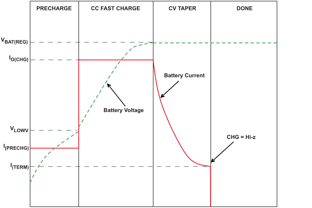
Typical charge cycle. (Figure 21 from the BQ27045 datasheet.)
The charger will be in pre-charge mode if the battery voltage is below about 3V. A battery this low on charge is in a fragile state and requires some delicate handling while it feeds on electrons to get back to a healthy level. In pre-charge mode, the charge current will be regulated to about 10% of the fast-charge current. For example, if the fast-charge current is set to 1.5A, the pre-charge current will be 150mA.
Fast-charge mode occurs while the battery voltage is between 3V and about 4.2V. During this state, the BQ27045 will charge the battery at constant current, determined by EN1 and EN2 (100mA, 500mA, or whatever the set fast-charge rate may be).
As the battery voltage nears 4.2V, the charge current will quickly taper off, as demonstrated in the graph above. In this state, the battery is held at a constant 4.2V.
The BQ24075's safety timers determine how long the BQ27045 can remain in either the pre-charge or fast-charge states, before giving up and shutting down. If a timer expires, the CHG LED will blink at 2Hz, and charging will be disabled. The timer can be cleared by toggling the CE pin from HIGH to LOW.
Setting the Saftey Timers
The length of the safety timers are determined by a resistor (or lack of resistor) connected to TMR. There are three timer-configuring options:
- Disable timer: Connect TMR to ground.
- Default timer: Leave TMR open.
- Custom timer: Connect a 18kΩ to 72kΩ resistor from TMR to ground to configure the timers.
The pre-charge and max-charge timers are set according to the following equations, based on a resistance from TMR to ground -- RTMR. (The calculated times are in seconds, resistance in ohms.)
tPRECHG = 0.048 × RTMR
tMAXCHG = 0.48 × RTMR
Resistor values between 18kΩ and 72kΩ can be added to set the maximum pre-charge time between 24-36 minutes, and the max-charge timer between 240 and 360 minutes.
As with customizing charge current, if you want to make a modification to the charge timers, you first need to cut the TMR jumper, then add an external resistor between TMR and ground.
Power-Path Management
One of the BQ24075's most unique features is dynamic power-path management (DPPM), which maintains a reliable output supply as long as either a battery or input supply (VIN/USB) are present.
The DPPM system can throttle charge current in order to maintain a reliable output supply. In the words of TI, DPPM "reduces the number of charge and discharge cycles on the battery," and it allows your project to "run with a defective or absent battery pack."
Footprints for a 0.1" header, 2-pin 3.5mm screw terminal and JST PTH connector are all connected to the power path management output.
Output Voltage Range
The output of the power-path management system is broken out to the "VOUT" pins, labeled "+" and "-". This supply output is active as long as either a battery or input supply are connected to the Battery Babysitter. (In the case of the battery-supply, the ON/OFF switch must be ON.) The voltage will swing between 3.0V and 5.5V, depending on the charge of your battery and the voltage/pressence of the input supply.
If the Battery Babysitter is powered by only a battery, the output voltage will usually be 50-100mV below the battery voltage. For example, a battery producing 3.75V might produce an output between 3.65 and 3.74V. A larger load, pulling more current, will create a bigger voltage drop.
If a 5V USB supply and battery are connected to the Babysitter, the output voltage will be somewhere between 3V and 5V, depending on the load, and charge percentage of the battery. If the battery is at, or near, full charge, the output could be as high as 5V. As the load increases, the voltage at the output supply will drop as low as 4.4V.
If your battery is charging, the output voltage will be around 4.3V, but may drop as low as 3.8V depending on the load.
TLDR
- If only a battery is present, the output should be about the battery voltage (minus a small drop).
- If battery and 5V USB are connected, and the battery is charging, the output will be 3.8 - 4.3V.
- If battery and 5V USB are connected, and the battery is fully charged, the output will be 4.5 - 5V.
Any load connected to VOUT should be able to handle a 3-5.5V input, but expect 3.6-5V assuming a healthy battery and USB supply. It's usually a good idea to regulate the output voltage of the Battery Babysitter to 3.3V, or find something that operates within the standard LiPo voltage range.
Power Path Operation Modes
The DPPM system is designed to protect a non-self-regulating charge supply by enforcing a limit on how much current that supply can source. Just as EN1 and EN2 are used to set charge current, they also control the input current limit:
| EN1 | EN2 | Power-Path Mode | Input Current Limit |
| 0 | 0 | Standby | USB suspend |
| 1 | 0 | DPPM | ILIM (1500 mA for ISET) |
| 0 | 1 | USB500 | 500 mA |
| 1 | 1 | USB100 | 100 mA (Default Charge Rate) |
These limits help guarantee that your input supply will not be tasked with sourcing more current than it's capable of.
If both VIN (USB or external) and a battery are connected and a load is pulling more than the set input current limit, the pair of supplies will supplement each other -- the input supply will source current to the set limit (100mA, 500mA, etc.), and the battery will take care of the rest.
Input Current-Limit Example
The DPPM's input current limits are designed to protect against over-loading a USB supply. If, for example, your Battery Babysitter is powering a project that is consistently drawing 1A and both a battery and USB supply are connected to the board, here is the current draw you might expect from the pair of supplies:
| Power-Path Mode | Current From Battery | Current From VIN (e.g. USB) |
|---|---|---|
| USB100 | 900 mA | 100 mA |
| USB500 | 500 mA | 500 mA |
| DPPM (set to 1.5A) | 0 mA | 1000 mA |
| Standby | 1000 mA | 0 mA |
Input Current Limit (ILIM)
An external resistor between the ILIM pin and ground is used to set the maximum input current in DPPM mode. This value is set by the following equation, where resistance is in ohms and current is in amps:
ILIM = 1550 / RILIM
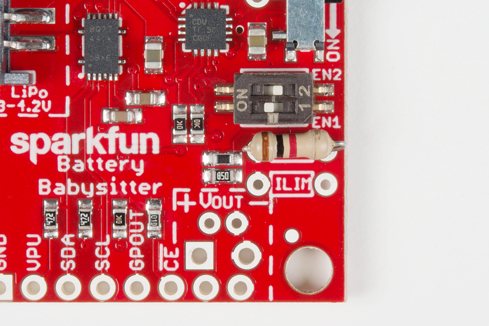
The Battery Babysitter populates this pin with a 1.1kΩ resistor, which sets the input current limit in DPPM mode to about 1.4A.
To customize this resistance value, as with the other charger features, cut the ILIM jumper on the back of the board. Then, calculate your desired current/resistance values, and populate a PTH resistor into the available ILIM resistor footprint.
LiPo Fuel Gauge
The Battery Babysitter's other predominant component is a BQ27441-G1A LiPo fuel gauge. With a highly sensitive analog-to-digital converter, it can measure a battery's voltage (mV) and state-of-charge (%). Plus, thanks to an external sense resistor, it can measure current (mA), power (mW), and even estimate remaining capacity (mAh).
The BQ27441 supports I2C, a two-wire serial interface, as its controlling interface. I2C is used to configure the fuel gauge with characteristics like full capacity, and it's used to read out all of the gauge's battery measurements.
The fuel gauge also features a programmable interrupt output, broken out to the GPOUT pin. This pin can be configured as either active-high or active-low, and it can be set to trigger when the battery charge falls below a set percentage or when the percentage changes by a set integer value.
Powering the BQ27441-G1A
The BQ27441-G1A LiPo fuel gauge is powered by the LiPo battery. To power its core logic, the fuel gauge regulates the battery voltage down to 1.8V. The 1.8V OUT pin on the side of the Battery Babysitter breaks out the fuel gauge's 1.8V output supply, but it is meant as more of a voltage reference than a power source.
Although the BQ27441-G1A runs at 1.8V, its I2C and GPOUT pins are tolerant up to 5V. That's where the VPU pin comes into play. The VPU pin, short for VPULL-UP, is the pull-up voltage for the open-drain SDA and SCL pins. This pin is an input, and should be connected to the operating voltage of your system -- 3.3V, 5V, etc. A voltage supply is required on this pin, unless you have pull-up's on the I2C bus elsewhere in your project.
Example Hardware Hookup
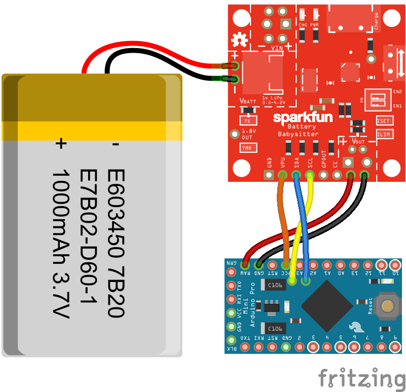
There are a variety of ways to integrate the Battery Babysitter into your project. Below is an foundational example circuit, which takes care of I2C wiring, but does not power the Arduino from the Babysitter.
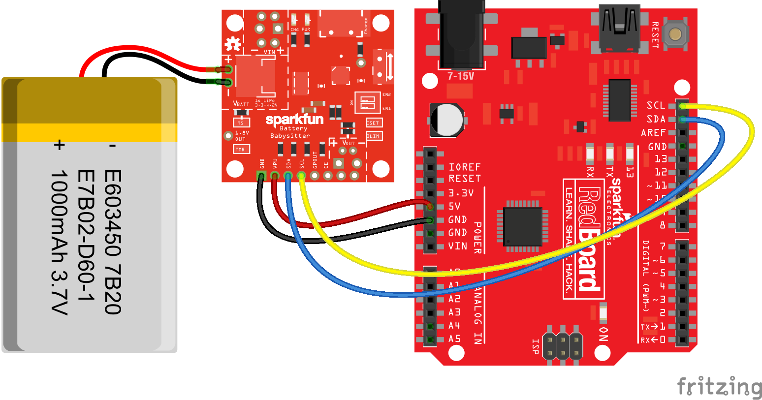
Optionally, a wire can be connected from the Battery Babysitter's VOUT pin to the Arduino's 5V pin -- powering the Arduino at somewhere between 3.4 and 5.5V. These pins should only be connected when the Arduino is not connected to USB, though; while you're testing out the I2C interface and using the serial monitor for debugging, it's best to leave that wire out.
Powering an Arduino From the Battery Babysitter
The Battery Babysitter is best-suited to powering 3.3V-based devices, like the Arduino Pro Mini 3.3V/8MHz, ESP8266 Thing, SAMD21 Mini Breakout, or Particle Photon. In those cases, you should be able to connect VOUT of the Battery Babysitter to your development board's "VIN" pin, where the Babysitter's output will be safely regulated down to 3.3V.
For example, here's the babysitter connected to an Arduino Pro Mini 3.3V:
When the Babysitter is powering a 5V-based Arduino – RedBoard, Arduino Uno, etc. – the Arduino's 5V regulator will be underpowered and will likely run close to the Battery Babysitter's output voltage, anywhere between 3.4-5V. That means an Arduino running at 16MHz may be underpowered.
BQ27441 Arduino Library
To make interfacing with the Battery Babysitter's BQ27441 LiPo fuel gauge as painless as possible, we've written an Arduino library to abstract away the unique I2C interface and register interfacing. Head over to the SparkFun_BQ27441_Arduino_Library GitHub repository to download the latest, greatest release, or click the button below to download the library in a ZIP file.
For help installing the library, check out our Installing an Arduino Library tutorial.
Start Simple: BQ27441_Basic Example
The library includes a handful of examples, which you're free to explore. To begin, we recommend BQ27441_Basic. Click through File > Examples > SparkFun BQ27441 LiPo Fuel Gauge Arduino Library > BQ27441_Basic to open it up.
Then set your Arduino port/board, and upload away!
After uploading, open up your serial monitor, and set the baud rate to 115200 bps. You should see the Arduino initialize the fuel gauge, and then begin printing some battery stats:
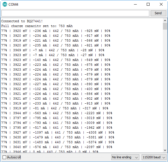
The basic example prints state-of-charge (%), battery voltage (mV), average current draw from the battery (mA), remaining and full capacities (mAh), average power draw on the battery (mW), and the battery's state-of-health (%). The current and power draws will be negative when the battery is sourcing current, and positive when it's charging. Try hooking up some power resistors to the Battery Babysitter's output, or start charging to see how these numbers change.
You can adjust the full capacity value by configuring the BATTERY_CAPACITY variable at the top of the example sketch. For example, by assigning that variable a value of 850, the sketch configures the BQ27441 to calculate the battery state assuming an 850 mAh battery is connected to it.
Using the BQ27441 Arduino Library
Here is a quick primer to incorporating the BQ27441 library into a sketch of your own. First, set the library up by including it. Then -- usually in the setup() function -- call lipo.begin(). You can check the return value of the begin function, to make sure the Battery Babysitter is connected correctly.
language:c
#include <SparkFunBQ27441.h>

void setup()
{
    Serial.begin(115200);
    if (!lipo.begin())
    {
        Serial.println("Error: Unable to communicate with BQ27441.");
        Serial.println("  Check wiring and try again.");
        Serial.println("  (Battery must be plugged into Battery Babysitter!)");
        while (1) ;
    }
    Serial.println("Connected to BQ27441!");
}
Next, you may want to set the battery's full capacity using the lipo.setCapacity() function:
language:c
lipo.setCapacity(1000); // Configure BQ27441 to assume a 1000 mAh battery
Expect a short delay -- 1-to-2 seconds -- before your Arduino completes the execution of this function. The Battery Babysitter's capacity setting will remain at the set value until it loses power (usually when a battery is disconnected or fully discharged).
After those quick function-calls, you're ready to read some battery statistics. You can use these functions to read state-of-charge, voltage, remaining capacity, current, power, and more.
language:c
unsigned int soc = lipo.soc(); // Read state-of-charge (in %)
unsigned int volts = lipo.voltage(); // Read voltage (in mV)
int current = lipo.current(AVG); // Read average current (in mA)
unsigned int capacity = lipo.capacity(REMAIN); // Read remaining capacity (in mAh)
int power = lipo.power(); // Read power consumption (in mW)
int health = lipo.soh(); // Read state-of-health (in %)
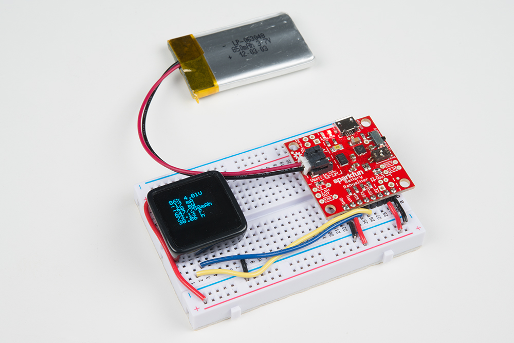
Now, take those values, and do something with them! Maybe that something is as simple as displaying the battery statistics on a MicroView.
Using GPOUT
The BQ27441’s programmable output – GPOUT – can be used to alleviate your microcontroller from constantly having to poll the fuel gauge. GPOUT can be configured to alert your Arduino of one of two state changes. To start using the pin, simply connect it to a free Arduino digital pin, and load up one of the examples.
Low Battery Alert
The GPOUT pin can be used to alert your system that the battery’s state-of-charge has fallen below a pair of values. You can set two SoC thresholds in this mode: a higher “SOC1” value, and a critically low “SOCF” value. For example, the SOC1 threshold might be 20%, while the SOCF threshold is 5%.
In this mode, when the battery voltage falls below a threshold the interrupt will activate. It will remain in that state until the battery is charged, and its SoC rises above the threshold.
This interrupt function is documented in the BQ27441_GPOUT_BAT_LOW example.
Change in State-of-Charge
Alternatively, the BQ27441 can be configured to trigger the GPOUT pin whenever the SoC goes up or down by a set integer value. That integer value can be configured between 1 and 100. So, for example, if the change-delta is set to 1, GPOUT will trigger every time the SoC goes up or down a percent – 0%, 1%, 2%, and so on. If the change-delta is set to 10%, the interrupt will fire every time the SoC rises or falls to a factor of 10: 0%, 10%, 20%, etc.
This interrupt function is documented in the BQ27441_GPOUT_SOC_INT example.
Resources and Going Further
The SparkFun Battery Babysitter and the BQ27441 Arduino Library are both open-source, so there are plenty of resources to go around, including:
- SparkFun Battery Babysitter Schematic (PDF)
- SparkFun Battery Babysitter Eagle Files (ZIP)
- SparkFun BQ27441 LiPo Fuel Gague Arduino Library GitHub Repository
- SparkFun Battery Babysitter GitHub Repository
- SFE Product Showcase
If you'd like to learn more about the BQ27441-G1A LiPo Fuel Guage, TI has published an excellent 59-page Technical Reference manual, plus, of course, there's the datasheet.
For more information on the BQ24075 LiPo charger, the datasheet should have all of the information you might need.
The Battery Babysitter can be incorporated into just about any LiPo-powered project out there. If you're looking for a little project-inspiration, check out some of these great SparkFun tutorials: