Basic LED Animations for Beginners (Arduino)
 Brandon J. Williams
Lights, Camera, ACTION
Blink like Booyah
Check out the circuit diagram below to see how everything is connected.
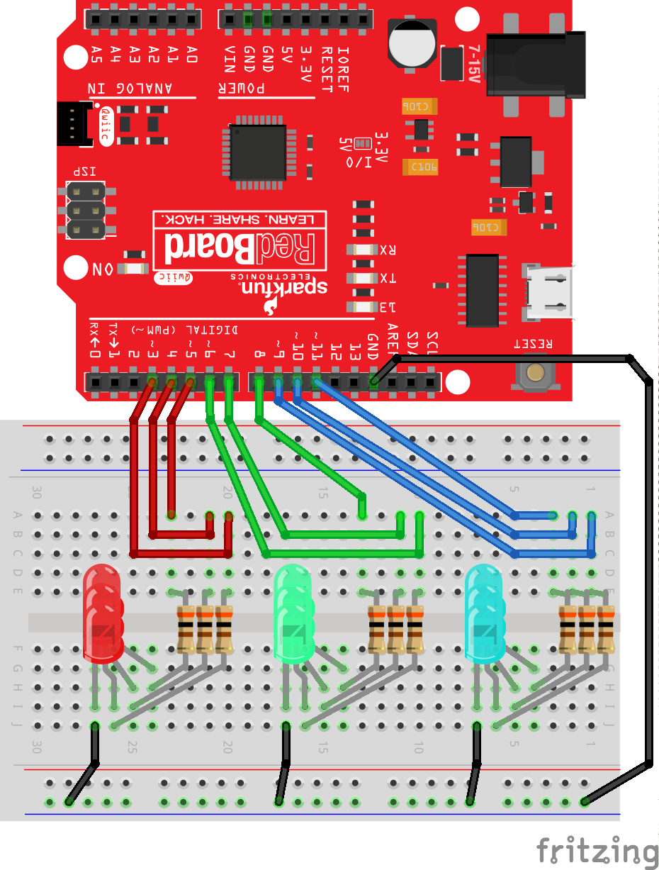
I had a liberty with having some fun with this one. We're turning on each LED set one by one. Once the set is turned on, we'll turn them each off one by one before moving to the next set.
Copy and paste the following code into the Arduino IDE. Hit upload, and see what happens!
language:c
//This example turns on each LED set one by one. Once the set is turned on, we'll turn them each off one by one before moving to the next set.

//Declare pins
const int GREEN_A = 8;
const int GREEN_B = 7;
const int GREEN_C = 6;
const int RED_A = 5;
const int RED_B = 4;
const int RED_C = 3;
const int BLUE_A = 11;
const int BLUE_B = 10;
const int BLUE_C = 9;

const int turn_time = 300;      //Play with this integer!!

void setup() {
  // initialize pins as output
  pinMode(GREEN_A, OUTPUT);
  pinMode(GREEN_B, OUTPUT);
  pinMode(GREEN_C, OUTPUT);
  pinMode(RED_A, OUTPUT);
  pinMode(RED_B, OUTPUT);
  pinMode(RED_C, OUTPUT);
  pinMode(BLUE_A, OUTPUT);
  pinMode(BLUE_B, OUTPUT);
  pinMode(BLUE_C, OUTPUT);
}

void loop() {
  //These sequences just turn on 3 of the same color one by one. Then turn them off
  //one by one.
  digitalWrite(BLUE_A, HIGH);   // turn the LED on (HIGH is the voltage level)
  delay(turn_time);                       // wait for a second
  digitalWrite(BLUE_B, HIGH);   // turn the LED on (HIGH is the voltage level)
  delay(turn_time);                       // wait for a second
  digitalWrite(BLUE_C, HIGH);   // turn the LED on (HIGH is the voltage level)
  delay(turn_time);                       // wait for a second
  digitalWrite(BLUE_A, LOW);    // turn the LED off by making the voltage LOW
  delay(turn_time);                       // wait for a second
  digitalWrite(BLUE_B, LOW);    // turn the LED off by making the voltage LOW
  delay(turn_time);                       // wait for a second
  digitalWrite(BLUE_C, LOW);    // turn the LED off by making the voltage LOW
  delay(turn_time);                       // wait for a second

  digitalWrite(GREEN_A, HIGH);   // turn the LED on (HIGH is the voltage level)
  delay(turn_time);                       // wait for a second
  digitalWrite(GREEN_B, HIGH);   // turn the LED on (HIGH is the voltage level)
  delay(turn_time);                       // wait for a second
  digitalWrite(GREEN_C, HIGH);   // turn the LED on (HIGH is the voltage level)
  delay(turn_time);                       // wait for a second
  digitalWrite(GREEN_A, LOW);   // turn the LED off (HIGH is the voltage level)
  delay(turn_time);                       // wait for a second
  digitalWrite(GREEN_B, LOW);   // turn the LED off (HIGH is the voltage level)
  delay(turn_time);                       // wait for a second
  digitalWrite(GREEN_C, LOW);   // turn the LED off (HIGH is the voltage level)
  delay(turn_time);                       // wait for a second

  digitalWrite(RED_A, HIGH);   // turn the LED on (HIGH is the voltage level)
  delay(turn_time);                       // wait for a second
  digitalWrite(RED_B, HIGH);   // turn the LED on (HIGH is the voltage level)
  delay(turn_time);                       // wait for a second
  digitalWrite(RED_C, HIGH);   // turn the LED on (HIGH is the voltage level)
  delay(turn_time);                       // wait for a second
  digitalWrite(RED_A, LOW);    // turn the LED off by making the voltage LOW
  delay(turn_time);                      // wait for a second
  digitalWrite(RED_B, LOW);    // turn the LED off by making the voltage LOW
  delay(turn_time);                      // wait for a second
  digitalWrite(RED_C, LOW);    // turn the LED off by making the voltage LOW
  delay(turn_time);                      // wait for a second

}
We should play with this one a bit. Change the value of turn_time. The delay() function takes these integer inputs and they represent milliseconds. 50 will go really quick, 5000 will go really slow.
Hypno-Toad
Check out the circuit diagram below to see how everything is connected.
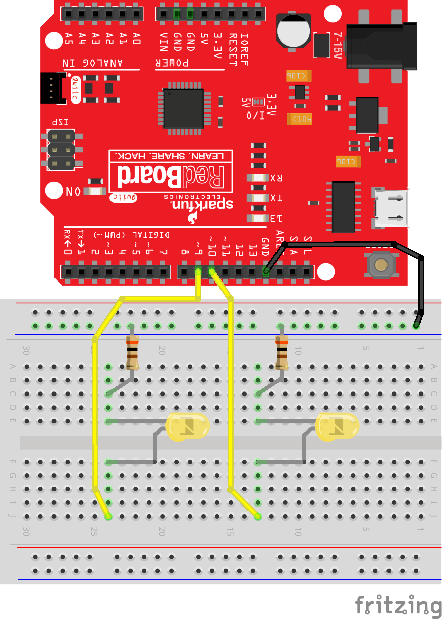
The Arduino IDE has really great entry level examples aside from blink. A favorite of mine is an LED Fade. We're going to modify it to fade two LEDs and use them as eyes. The fade function relies on analogWrite(). This function outputs a Pulse Width Modulation (PWM) signal. At low integer values the signal will make the LED dim, and will make the LED bright at high integer values.
Copy and paste the following code into the Arduino IDE. Hit upload, and see what happens!
language:c
//This example fades an LED on and off. Then the other LED will fade in and out.

//Declare pins and variables
const int ledA = 9;
const int ledB = 10;
int brightness = 0;
int fadeAmount = 5;

void setup() {

  //Declare pins as outputs
  pinMode(ledA, OUTPUT);
  pinMode(ledB, OUTPUT);
}

void loop() {

  //ledA will fade on
  for (int i = 0; i <= 255;) {
    analogWrite(ledA, brightness);
    brightness += fadeAmount;
    i += fadeAmount;
    delay(30);
  }

  //ledA will fade off
  for (int i = 255; i >= 0;) {
    analogWrite(ledA, brightness);
    brightness -= fadeAmount;
    i -= fadeAmount;
    delay(30);
  }

  //ledB will fade on
  for (int j = 0; j <= 255;) {
    analogWrite(ledB, brightness);
    brightness += fadeAmount;
    j += fadeAmount;
    delay(30);
  }

  //ledB will fade off
  for (int j = 255; j >= 0;) {
    analogWrite(ledB, brightness);
    brightness -= fadeAmount;
    j -= fadeAmount;
    delay(30);
  }

}
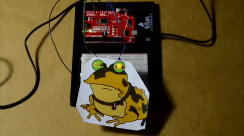
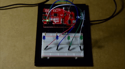
You should see one LED fade on and off. Then the other LED will fade in and out. I printed a popular cartoon image and punched holes through the eyes for the LEDs. Try searching the Internet for a fun image and make some holes yourself. You may need to adjust the size of the image and position of the LEDs to align the eyes. Go crazy with it!
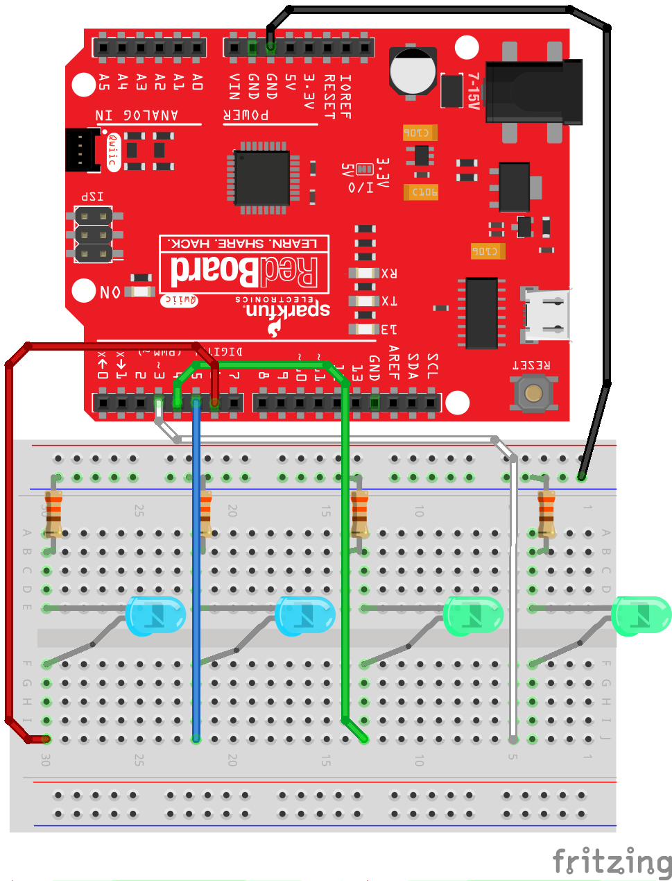
Binary Counter
A not so glamorous topic in computer science are binary numbers, a.k.a the infamous 1's and 0's. When we count in binary, we represent numbers with arrangments of 1's and 0's. For example, if I wanted to write the number 4, I would need a 'binary sentence' of 0100. If you'd like to learn more about binary numbers, we have a tutorial about binary numbers that you can explore.
The binary project we'll run today will use the LEDs to represent 1's and 0's. An LED that's on is a 1, off will be a 0. Also, a special note about the code, we'll be using switch statements instead of if() statements. If you're not familiar with switch statements, please make sure to check out the Arduino reference language to familiarize yourself.
Check out the circuit diagram below to see how everything is connected.
Copy and paste the following code into the Arduino IDE. Hit upload, and see what happens!
language:c
//This example toggles uses LEDs as a binary counter.

//Declare pins
const int ledA = 3; //In binary, this pin will be the right-most digit or 1st position
const int ledB = 4; //2nd position
const int ledC = 5; //3rd position
const int ledD = 6; //4th position

void setup() {
  //Declare pins as outputs
  pinMode(ledA, OUTPUT);
  pinMode(ledB, OUTPUT);
  pinMode(ledC, OUTPUT);
  pinMode(ledD, OUTPUT);
}

void loop() {
  for (int i = 0; i < 16; i++) {
    switch (i) {
      case 0:  //0 = 0b0000
        delay(1000);
        digitalWrite(ledA, LOW);
        digitalWrite(ledB, LOW);
        digitalWrite(ledC, LOW);
        digitalWrite(ledD, LOW);
        break;

      case 1: //1 = 0b0001
        digitalWrite(ledA, HIGH);
        delay(1000);
        digitalWrite(ledA, LOW);
        break;

      case 2: //2 = 0b0010
        digitalWrite(ledB, HIGH);
        delay(1000);
        digitalWrite(ledB, LOW);
        break;

      case 3: //3 = 0b0011
        digitalWrite(ledA, HIGH);
        digitalWrite(ledB, HIGH);
        delay(1000);
        digitalWrite(ledA, LOW);
        digitalWrite(ledB, LOW);
        break;

      case 4: //4 = 0b0100
        digitalWrite(ledC, HIGH);
        delay(1000);
        digitalWrite(ledC, LOW);
        break;

      case 5: //5 = 0b0101
        digitalWrite(ledA, HIGH);
        digitalWrite(ledC, HIGH);
        delay(1000);
        digitalWrite(ledA, LOW);
        digitalWrite(ledC, LOW);
        break;

      case 6: //6 = 0b0110
        digitalWrite(ledB, HIGH);
        digitalWrite(ledC, HIGH);
        delay(1000);
        digitalWrite(ledB, LOW);
        digitalWrite(ledC, LOW);
        break;

      case 7: //7 = 0b0111
        digitalWrite(ledA, HIGH);
        digitalWrite(ledB, HIGH);
        digitalWrite(ledC, HIGH);
        delay(1000);
        digitalWrite(ledA, LOW);
        digitalWrite(ledB, LOW);
        digitalWrite(ledC, LOW);
        break;

      case 8: //8 = 0b1000
        digitalWrite(ledD, HIGH);
        delay(1000);
        digitalWrite(ledD, LOW);
        break;

      case 9: //9 = 0b1001
        digitalWrite(ledA, HIGH);
        digitalWrite(ledD, HIGH);
        delay(1000);
        digitalWrite(ledA, LOW);
        digitalWrite(ledD, LOW);
        break;

      case 10: //10 = 0b1010
        digitalWrite(ledB, HIGH);
        digitalWrite(ledD, HIGH);
        delay(1000);
        digitalWrite(ledB, LOW);
        digitalWrite(ledD, LOW);
        break;

      case 11: //11 = 0b1011
        digitalWrite(ledA, HIGH);
        digitalWrite(ledB, HIGH);
        digitalWrite(ledD, HIGH);
        delay(1000);
        digitalWrite(ledA, LOW);
        digitalWrite(ledB, LOW);
        digitalWrite(ledD, LOW);
        break;

      case 12: //12 = 0b1100
        digitalWrite(ledC, HIGH);
        digitalWrite(ledD, HIGH);
        delay(1000);
        digitalWrite(ledC, LOW);
        digitalWrite(ledD, LOW);
        break;

      case 13: //13 = 0b1101
        digitalWrite(ledA, HIGH);
        digitalWrite(ledC, HIGH);
        digitalWrite(ledD, HIGH);
        delay(1000);
        digitalWrite(ledA, LOW);
        digitalWrite(ledC, LOW);
        digitalWrite(ledD, LOW);
        break;

      case 14: //14 = 0b1110
        digitalWrite(ledB, HIGH);
        digitalWrite(ledC, HIGH);
        digitalWrite(ledD, HIGH);
        delay(1000);
        digitalWrite(ledB, LOW);
        digitalWrite(ledC, LOW);
        digitalWrite(ledD, LOW);
        break;

      case 15: //15 = 0b1111
        digitalWrite(ledA, HIGH);
        digitalWrite(ledB, HIGH);
        digitalWrite(ledC, HIGH);
        digitalWrite(ledD, HIGH);
        delay(1000);
        digitalWrite(ledA, LOW);
        digitalWrite(ledB, LOW);
        digitalWrite(ledC, LOW);
        digitalWrite(ledD, LOW);
        break;
    }
  }
  delay(500);
}
With the blue LEDs to your left, you should see the LEDs slowly count up in binary and repeat the sequence. Try adding more LEDs and switch cases to see if you can increase the binary counter!
ledD, ledC, ledB, ledA.