AST-CAN485 WiFi Shield Hookup Guide
Contributors:
 Alex the Giant, Ell C, JamesBM
Hardware Hookup
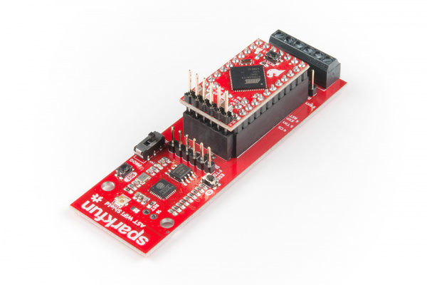
The AST-CAN485 WiFi Shield comes with headers pre-soldered to the board. Insert the CAN485 as shown with the CAN485's FTDI header close to the ESP8266.
Powering The Board
The Shield can be powered through the screw terminals. While the power input is intended to be supplied with 24V, an input voltage of 7-24V may be used.
An integrated power supply regulates the 24V input power down to 5V which is used to provide power to the inserted CAN485 board. This is further regulated down to 3.3V to power the ESP module.
It is also possible to power the board using the raw input pin of the CAN485 module. However, use of an external 24V supply is recommended and is the intended use case.
Image courtesy of AST
⚡ Warning! This board has pins that operate at 24V as well as pins that operate at 5V and 3.3V. Care should be taken during wiring as 24V has the potential to do significant damage to 5V and 3.3V circuits.

