AST-CAN485 Hookup Guide
Introduction to CAN Bus
The Controller Area Network (CAN) bus is a communications standard with its origins in the automotive industry. It has several built in features that make it robust and noise tolerant. It is a message based protocol that is able to support multiple nodes. Speeds up to 1Mbps are supported over distances less than 40m while longer distances are possible at lower speeds (500m at 125Kbps). CAN bus also features an arbitration method which automatically prioritizes messages and resolves packet collisions.
CAN is used as a field bus in industrial applications and comprises the lower layer on top of which many higher-layer protocols are based. CANopen and DeviceNet are common higher layer protocols based on CAN bus and used in industrial automation. CAN bus is also used in the OBDII vehicle diagnostics standard which is mandatory on modern cars in the US and EU.
Signal Description
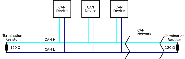
A CAN bus consists of two signals (CAN H and CAN L) and terminated at each end with a termination resistor (typically 100Ω to 120Ω). For high speeds, it is recommended to to have a 120Ω termination resistor. These lines are usually wound into a twisted pair.
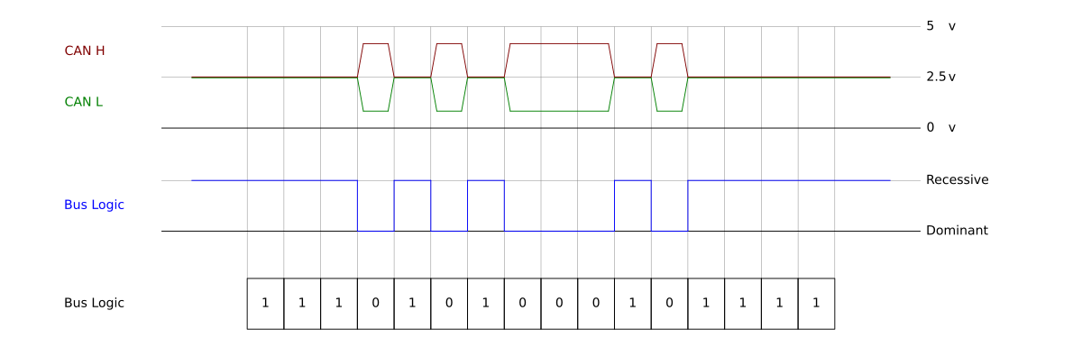
The bus has a recessive state (Logic 1) and a dominant state (logic 0). The bus needs to be actively driven to the dominant state by one of the nodes. If it is not driven to the dominant state by any of the nodes, the bus will return to the recessive state. This dominant and recessive behavior means that if two nodes transmit at the same time, the dominant bits will take preference. A method of arbitration takes advantage of this behavior to resolve packet collisions.
A CAN transceiver is necessary to translate between the line states and the logical states used by a microprocessor.
Network Structure
Multiple nodes may be connected in parallel. The lines must be terminated on each end with a termination resistor (typically 100Ω to 120Ω). For high speed CAN bus, the network below included a termination resistor of 120Ω at each end.
Packet Structure
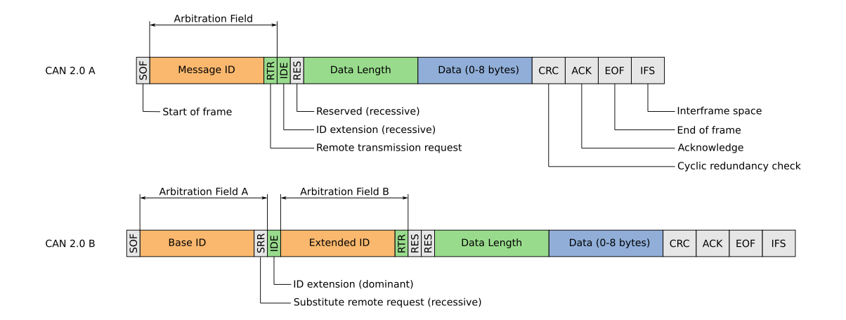
CAN messages have a standard format consisting of a message ID, a data length field, a data frame, a CRC and other control bits. Being a message based protocol, there are no node addresses, instead there is a message ID. Data is associated with an ID as opposed to a device and one node may transmit using several message IDs. This behavior can be very useful. For example, a node can report motor speed, position and acceleration on three different message IDs, allowing for easy identification of parameters by any receiving nodes.
Message IDs should be unique. If two nodes attempt to send a message with the same ID at the same time, it will cause an error. The message ID is also used in the arbitration process to determine which message has priority when two nodes attempt to transmit at the same time.
There are two standard formats for CAN packets, the base format (CAN2.0A) and the extended format (CAN2.0B). The extended format features a 29-bit ID while the base format features an 11-bit ID. The extended format is backwards compatible, allowing for both formats to be used on any CAN network.
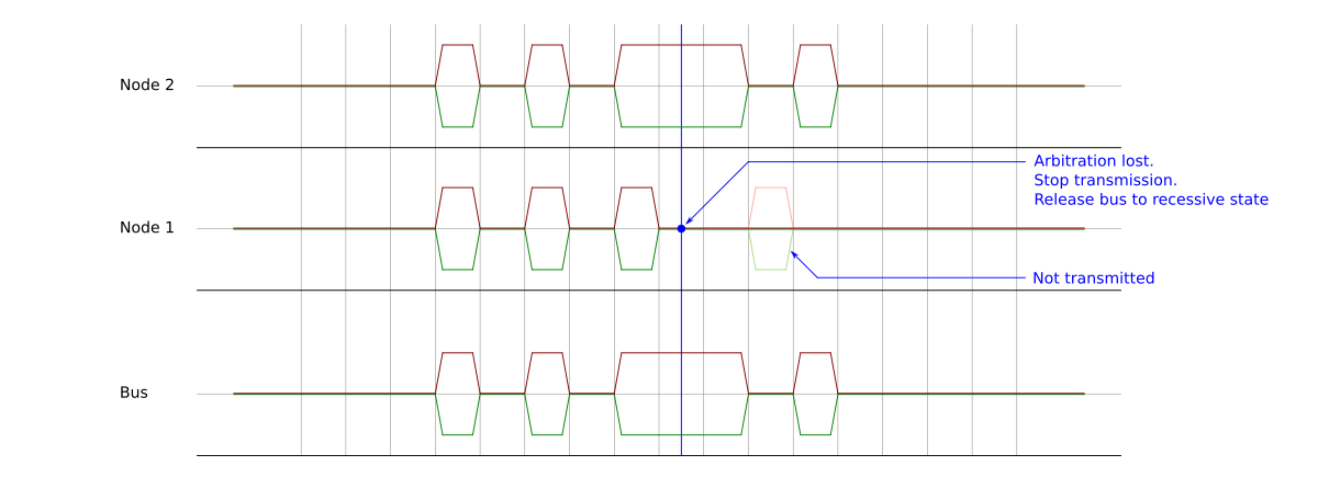
Arbitration
When two nodes attempt to transmit at the same time an arbitration process determines which one takes preference. While transmitting, each node reads the bus state as well. If a node detects that one of its recessive bits has been driven dominant by another node, then it stops transmitting. This results in lower IDs taking precedence over higher IDs. If a node looses arbitration, it will attempt to resend the message once the current transmission is complete. This behavior results in automatic prioritization and collision resolution.