ARGOS ARTIC R2 Satellite Transceiver Shield Hookup Guide
 PaulZC
 Introduction
Looking for a satellite communication board for your next project? This could be the one!
We offer three ARGOS ARTIC R2 satellite transceiver products:
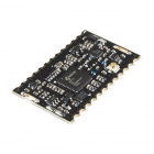
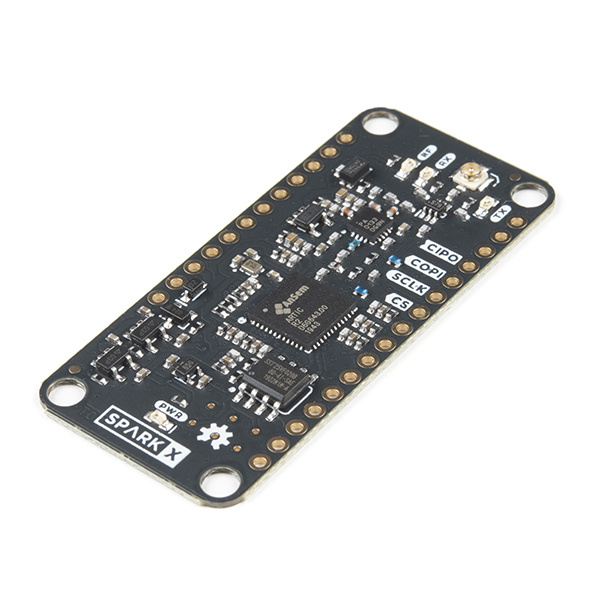
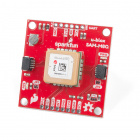
This board, the ARGOS Satellite Transceiver Shield - ARTIC R2, is the biggest of the three and the easiest to get your fingers around! It has the same footprint as our Feather-compatible Thing Plus boards and is designed to stack directly on top of a Thing Plus for easy development. If you are looking for a board to allow you to get to know how ARGOS satellite communication works, or are just starting out on your product development, or want a board you can plug into breadboard, or are not worried about making your tracking system as compact as possible, then this is the board for you!
The IOTA - the Integrated Open source Transceiver for ARGOS - is ideal if you are ready to incorporate an ARGOS transceiver into your design. Its castellated pads can be reflowed or hand-soldered as required. It also has slots for an RF screening can, should your certification process require one. The antenna connection is available on both a castellated pad and a u.FL connector.
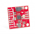
The smôl ARTIC R2 is the baby of the three, but it still packs the same punch as its larger siblings. If you are developing a compact dart for whale tracking, or a small backpack for avian tracking, or a very discrete satellite tracker, then the smôl ARTIC R2 is the one for you.

All three boards use the same ARTIC R2 satellite transceiver chip. All three have the same power amplifier, with the same maximum output power and adjustable gain. All three have the same receive sensitivity. All three have on-board flash memory containing the ARTIC R2 firmware and Platform ID. All three are supported by our comprehensive Arduino Library which includes a full set of tried-and-tested examples.
If you would like to know more about the ARGOS satellite network itself, head on over to our ARGOS (ARTIC R2) Satellite Communication Guide:
ARGOS & ARTIC R2
The ARGOS satellite system has been around for quite a while. It was created in 1978 by the French Space Agency (CNES), the National Aeronautics and Space Administration (NASA) and the National Oceanic and Atmospheric Administration (NOAA), originally as a scientific tool for collecting and relaying meteorological and oceanographic data around the world. Today, ARGOS is revolutionising satellite communication, adding a constellation of 25 nanosatellites to complement the 7 traditional satellites carrying ARGOS instrumentation. The first of these, ANGELS, is already in operation and SparkFun were among the first users to transmit data to ANGELS in October 2020. When the constellation is complete, there will be a maximum of 10-15 minutes between satellite passes.
The ARTIC R2 is an integrated, low-power, small-size ARGOS 2/3/4 single chip transceiver. ARTIC implements a message based wireless interface. For satellite uplink communication, ARTIC will encode, modulate and transmit provided user messages. For downlink communication, ARTIC will lock to the downstream, demodulate and decode and extract the satellite messages. The ARTIC can transmit signals in frequency bands around 400MHz and receive signals in the bands around 466MHz, in accordance with the ARGOS satellite system specifications.
Our ARTIC R2 Satellite Transceiver Shield has been tested and certified by Kinéis. Compared to other satellite communication systems, the ARTIC R2 has a much lower current draw and will work with a very simple, very lightweight quarter-wave wire antenna. The ARTIC R2 chipset on our board operates from 3.3V and the on-board flash memory enables fast boot times. If you don’t need the full transmit power, or want to conserve your battery life, you can transmit at reduced power too thanks to opto-isolated gain control.
Our Arduino Library makes it really easy to get up and running with ARGOS. We’ve provided a full set of examples which will let you: configure the ARTIC R2 chipset; predict the next satellite pass; receive allcast and individually-coded messages; transmit messages using ARGOS 2, 3 and 4 encoding.
Hardware Overview
In this section we'll cover what's included on the ARGOS ARTIC R2 Satellite Transceiver Shield.
ARTIC R2
The heart of the ARGOS ARTIC R2 Satellite Transceiver Shield is, of course, the ARTIC R2 transceiver itself. This is a clever chip containing a Digital Signal Processor (DSP) which modulates transmit messages and demodulates received messages. The DSP can boot from on-board flash memory or from an external microcontroller via SPI. When transmitting, it produces a 1mW (0dBm) output signal which is fed to a separate power amplifier.
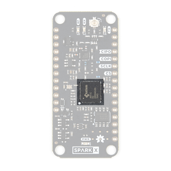
Our Arduino Library does all of the heavy lifting for you. By default, the library will tell the ARTIC R2 DSP to boot from the on-board flash memory. However, by changing one line of code, you can instead boot via SPI with your microcontroller providing the firmware for the DSP.
RF Amplifier
During transmit, the RFPA0133 power amplifier boosts the 0dBm (1mW) signal from the ARTIC R2.
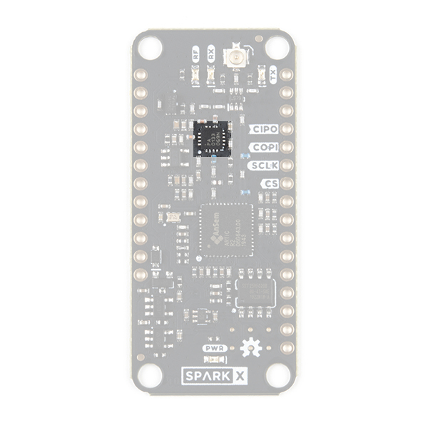
Using full gain, the amplifier boosts the signal to approximately 25.8dBm (380mW). If you are using ARGOS 2 or 3 modulation and are transmitting from a 'noisy' environment, like a city, then you are probably going to need to use full power to ensure your messages get through. However, if you are using ARGOS 4 modulation and/or are transmitting from a 'quiet' environment, like the tundra or the ocean, then you will be able to transmit at reduced power.
Gain Control
You can adjust the transmit gain through software and the on-board opto-isolated gain control circuit.
Our Arduino Library can reduce the gain for you. If you call:
language:c
myARTIC.attenuateTXgain(true);
from inside your code, the opto-isolator will pull the RFPA0133's G8 pin low, reducing the gain by approximately 5dB. This also has the advantage of reducing the transmit current by approximately 80mA.
Flash Memory
By default, the DSP inside the ARTIC R2 will boot from the on-board flash memory. (But, as mentioned above, you also have the option of booting via SPI.)
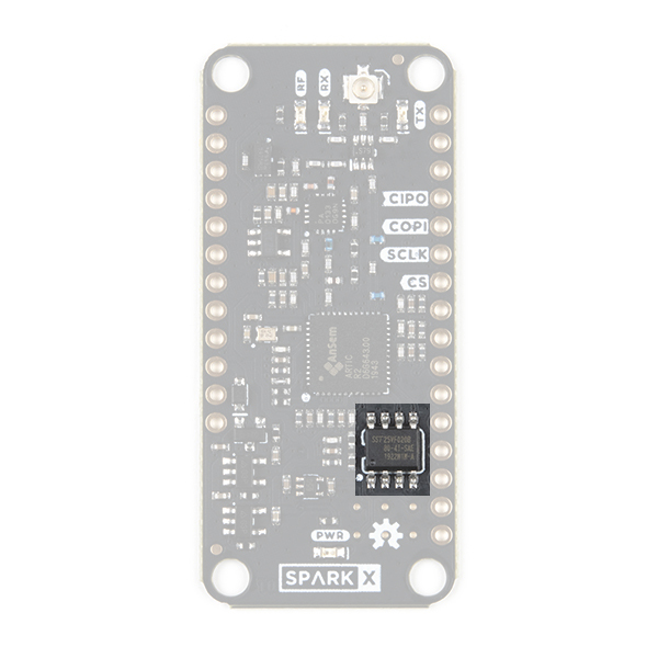
During production testing at SparkFun, we program the flash memory with the ARTIC R2 firmware (ARTIC006) and a Platform ID allocated by CLS. You will need to register the Platform ID on your ARGOS account to activate it. The Arduino Library reads the Platform ID from memory and uses it in the transmissions.
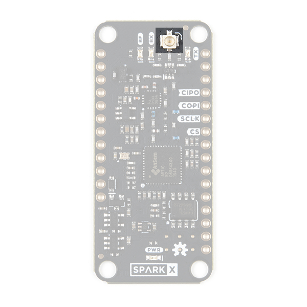
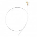
Antenna
The antenna connection for the ARTIC R2 is u.FL.
Check out our tutorial if you haven't used u.FL before:
Three Quick Tips About Using U.FL
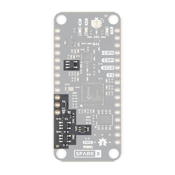
Power Circuit
The ARGOS ARTIC R2 Satellite Transceiver Shield can draw power from the standard Thing Plus / Feather VUSB and/or VBATT pins. The shield will preferentially draw 5V power from VUSB if connected, but can also be powered by a standard 3.6V LiPo battery via VBATT.
The power circuit comprises: an automatic switching circuit to select VUSB or VBATT; 3.3V, 3.0V and 1.8V regulators.
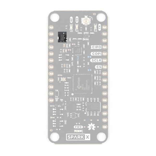
LEDs
The ARGOS ARTIC R2 Satellite Transceiver Shield has four LEDs which indicate if the board is powered and if it is transmitting or receiving.
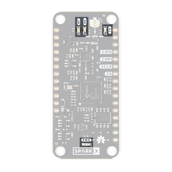
When lit, the LEDs indicate:
- RF: RF amplifier is powered on
- RX: ARTIC R2 is receiving
- TX: ARTIC R2 is transmitting
- PWR: ARTIC R2 shield power circuit is on
If you want to save power, you can disable the LEDs by cutting the jumper links on the back of the board:
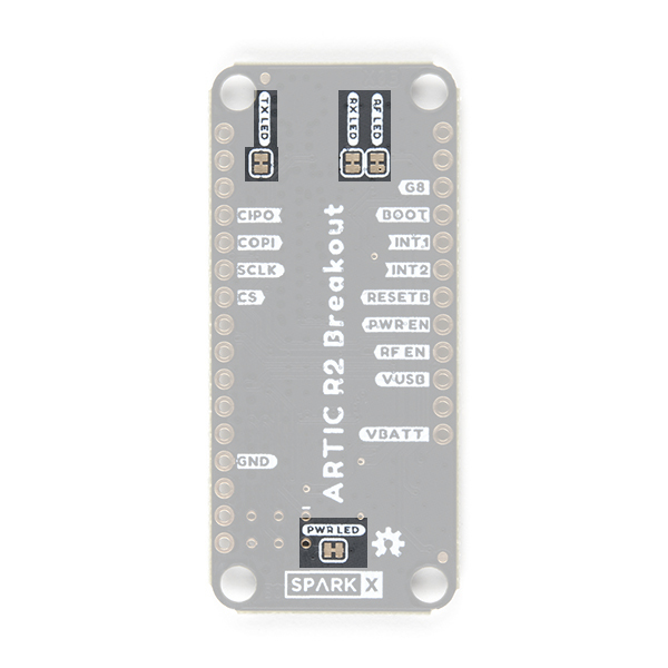
If you haven't worked with jumpers before, please check out our tutorial.
How to Work with Jumper Pads and PCB Traces
Breakout Pins
The table below describes the function of each of the ARGOS ARTIC R2 Satellite Transceiver Shield breakout pins:
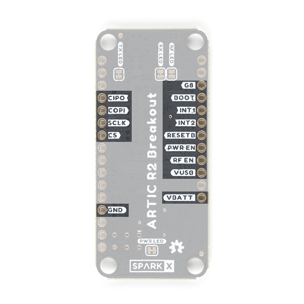
| Pin Name | Function | Description | Notes |
|---|---|---|---|
| CIPO | Output | SPI interface: Controller In Peripheral Out. | Logic level is 3.3V. |
| COPI | Input | SPI interface: Controller Out Peripheral In. | Logic level is 3.3V. |
| SCLK | Input | SPI interface clock signal. | Logic level is 3.3V. Typically 1MHz. See the ARTIC R2 datasheet for the permitted clock speeds. |
| CS | Input | SPI interface chip select. | Logic level is 3.3V. |
| GND | Power ground / 0V. | ||
| G8 | Input | Gain control. | Logic level is 3.3V. Pull high to set the RFPA0133 transmit power to maximum. The transmit power will be reduced by approximately 5dB if this pin is pulled low or left open. |
| BOOT | Input | Connected to the ARTIC R2 BOOT pin. | Logic level is 3.3V. Pulled high via a 100k resistor. When high, the ARTIC boots from the on-board flash memory. Pull low if the ARTIC firmware will be downloaded by the MCU via SPI. |
| INT1 | Output | Connected to the ARTIC INT1 pin. | Logic level is 3.3V. Will be pulled high by the ARTIC to indicate (e.g.) an RX_VALID_MESSAGE. |
| INT2 | Output | Connected to the ARTIC INT2 pin. | Logic level is 3.3V. Will be pulled high by the ARTIC to indicate (e.g.) an RX_BUFFER_OVERFLOW. |
| RESETB | Input | Connected to the ARTIC reset pin. | Logic level is 3.3V. Pulled high via a 100k resistor. Pull low to reset the ARTIC. |
| PWR EN | Input | Shield power circuit enable. | Logic level is 3.3V. Pulled low via a 100k resistor. Pull high to enable power for the ARTIC R2. |
| RF EN | Input | RF Amplifier enable. | Logic level is 3.3V. Pulled low via a 100k resistor. Pull high to enable power for the RF amplifier. |
| VUSB | Power | Power input from (e.g.) USB. | Typically 5V. 6.5V maximum. |
| VBATT | Power | Power input from (e.g.) a LiPo battery. | Typically 3.6V - 4.2V. 6.5V maximum. |
Power can be provided via the VBATT pin or the VUSB pin, or both. The shield will preferentially draw power from USB if connected. On-board 3.3V and 1.8V regulators regulate USB or battery power for the ARTIC R2 and RF amplifier. See below for the typical VBATT current draw.
Hardware Hookup
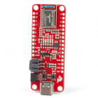
The ARGOS ARTIC R2 Satellite Transceiver Shield is designed to be mounted directly on top of one of our Feather-compatible Thing Plus boards. You will find that the examples in the Arduino Library are written for the SparkFun Thing Plus - Artemis but they can be adapted for any board by changing the pin definitions in the code. If you are looking for a works-out-of-the-box solution then the SparkFun Thing Plus - Artemis is the one to go for.
If you are looking for a complete kit to get you started, here are the parts you will need:


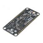
If you want to add GNSS functionality to your kit, so you can transmit your location accurately and/or predict the next satellite pass based on your location, you will also need (e.g.):

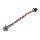
Qwiic Cable - 100mm
PRT-14427or:
Our favorite way to connect the ARGOS Shield to the Thing Plus Artemis is to use stacking headers. Solder lengths of our Female Headers onto the top of the Thing Plus Artemis. (This will allow you to connect jumper wires to the board if you want to.) Solder lengths of our male Break Away Headers - Straight to the underside of the ARGOS Shield. (This will allow you to mount the shield on breadboard too if you want to.) That's all the soldering done. If you haven't soldered before, you will find our tutorial useful:
How to Solder: Through-Hole Soldering
Mate the two boards together and voilà, you're just about ready to rock!
Connect your ARGOS antenna to the shield before you forget!
If you connect your LiPo battery to the Thing Plus Artemis now, it will recharge while you have USB power connected.
You won't need the GNSS receiver to begin with, but if you want to hook it up now, go right ahead! For the ZOE-M8Q, the GNSS antenna clips onto the u.FL connector on the GNSS board. Check out our tutorial if you haven't used u.FL before:
Three Quick Tips About Using U.FL
Connect the GNSS board to the Thing Plus using the Qwiic cable (which provides both power and I2C data).
Finally, the USB-C cable connects the Thing Plus to your computer. If you haven't used a CH340 USB interface before, you will want to install the driver first. The following section describes how to do that.
Jumper Wire Connections
If you have used the recommended Thing Plus Artemis and stacking headers, you don't need to worry about which signals to connect. It's all done for you. However, if you want to use a different Arduino board and connect your shield using jumper wires, here are the connections:
- Power:
- Connect GND to a GND (Ground) / 0V pin on your Arduino board
- If you want your Arduino board to provide power to the ARGOS ARTIC R2 Shield, we recommend connecting the Shield's VUSB pin to the 5V pin on your Arduino board
- SPI:
- Connect CIPO, COPI and SCLK to the SPI pins on your Arduino board
- Connect the CS (Chip Select) pin to a suitable I/O pin
- I/O (Essential):
- Connect the RESETB, BOOT, PWR EN, RF EN, INT1 and INT2 pins to suitable I/O pins on your Arduino board. Make a note of the pin numbers as you will need to enter them into the code.
- I/O (Optional):
- Connect the G8 gain control pin to another I/O pin on your Arduino board if you want to be able to control the transmit gain via software. If you leave this pin floating, the RF amplifier will transmit at reduced gain. Pull this pin up to 3.3V to transmit at maximum gain.
Note: Feather and Thing Plus Pins
On some Feather and Thing Plus boards, you may find that the pin below the ARGOS Shield's RF EN pin is digital pin 13 and also connected to the board's built-in LED. On some boards, the LED is flashed rapidly while the bootloader is running and code is being uploaded to the board. This will cause the Shield's RF power circuit to be turned on and off rapidly. While this is unlikely to damage the RF amplifier, it is best avoided. SAMD-based boards are the worst offenders.
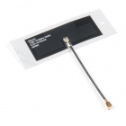
Note: Molex GNSS Antenna
Our Molex GNSS Antenna is very lightweight and is self-adhesive. It is an ideal choice for miniature satellite tracker projects. However, the antenna works best when located at least 40mm away from a ground plane. Don't be tempted to stick the antenna to a ground plane, metallic case or even your LiPo battery. If you do, you will get little or no GNSS signal. Please consult the application specification for more details.
Software Setup
If you are new to Arduino and the IDE, this guide will get you up and running:
Installing Arduino IDE
If you haven't installed an Arduino Library before, this is the guide you need:
Installing an Arduino Library
If you haven't used the Artemis Thing Plus before, this guide will tell you everything you need to know:
Hookup Guide for the SparkFun Artemis Thing Plus
You can find more specific information on how to install the Arduino Core for Artemis (Apollo3) in this guide. The section on Arduino Installation is the one to read in detail.
Artemis Development with Arduino
The Artemis Thing Plus uses a CH340 interface chip to communicate on USB. If you haven't installed drivers for the CH340 previously, this guide will tell you everything you need to know:
How to Install CH340 Drivers
Checklist
- Install the Arduino IDE
- Add the SparkFun Boards to the Preferences\Additional Board Manager URLs and install the SparkFun Apollo3 board package
- Close the IDE
- Install the CH340 COM port drivers
- Reopen the IDE
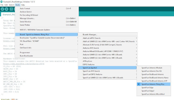
- Click on Tools\Board and select SparkFun Apollo3\SparkFun Artemis Thing Plus
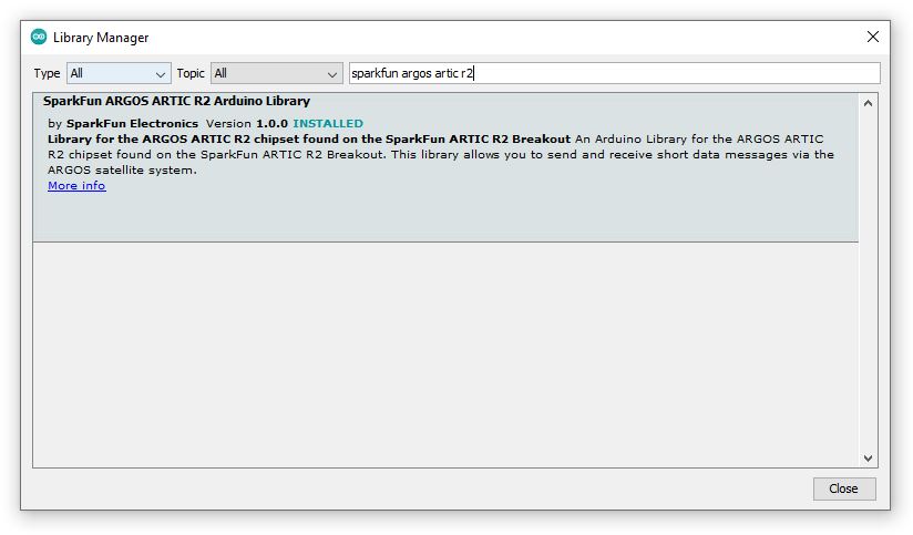
- Click on Tools\Manage Libraries... to open the library manager
- In the search box, type SparkFun ARGOS ARTIC R2
- Click the Install button to install the ARGOS ARTIC R2 library
- If your shield came with an ARGOS Platform ID card showing which ID is pre-programmed into the shield's flash memory, you can install the latest version of the library
Alternatively, you can grab the library directly from GitHub or can download it as a zip file by clicking the button below:
If you have a board from the first batch we manufactured, you can download a zip file of v1.0.9 of the library by clicking the link below:
- Attach the Thing Plus to your computer using a USB-C cable
- If you are using Windows, you should hear the usual USB-connection chime
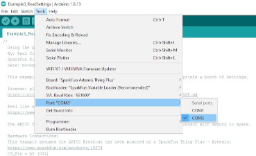
- Click on Tools\Port and select the COM port for the Artemis
Arduino Example: Satellite Detection
The SparkFun ARGOS ARTIC R2 Arduino Library contains a full set of tried and tested examples which will run on the Artemis Thing Plus when connected to the ARTIC R2 Shield. The examples will run on other Arduino boards, but you will need to change the pin definitions in the code to match your board.
The code below is a stripped-down version of Example4_SatelliteDetection. Copy and paste the code into a new window in the Arduino IDE:
language:c
#include <SPI.h>
#include "SparkFun_ARGOS_ARTIC_R2_Arduino_Library.h" // http://librarymanager/All#SparkFun_ARGOS_ARTIC_R2
ARTIC_R2 myARTIC;

// Pin assignments for the SparkFun Thing Plus - Artemis
// (Change these if required)
int CS_Pin = 24;
int GAIN8_Pin = 3;
int BOOT_Pin = 4;
int INT1_Pin = 5;
int INT2_Pin = 6;
int RESET_Pin = 7;
int ARTIC_PWR_EN_Pin = 8;
int RF_PWR_EN_Pin = 9;

void setup()
{
  Serial.begin(115200);
  Serial.println(F("ARGOS ARTIC R2 Example"));

  Serial.println(F("ARTIC R2 is booting..."));

  SPI.begin();

  //myARTIC.enableDebugging(); // Uncomment this line to enable debug messages on Serial

  // Begin the ARTIC: enable power and boot from flash
  if (myARTIC.begin(CS_Pin, RESET_Pin, BOOT_Pin, ARTIC_PWR_EN_Pin, RF_PWR_EN_Pin, INT1_Pin, INT2_Pin, GAIN8_Pin) == false)
  {
    Serial.println("ARTIC R2 not detected. Freezing...");
    while (1)
      ; // Do nothing more
  }

  Serial.println(F("ARTIC R2 boot was successful."));

  // Read the Platform ID from flash memory
  uint32_t platformID = myARTIC.readPlatformID();
  if (platformID == 0)
  {
    Serial.println(F("You appear to have an early version of the SparkFun board."));
    Serial.println(F("For the transmit examples, you will need to use the Library Manager to select version 1.0.9 of this library."));
  }
  else
  {
    Serial.print(F("Your Platform ID is: 0x"));
    Serial.println(platformID, HEX);
  }

  myARTIC.setTCXOControl(1.8, true); // Set the TCXO voltage to 1.8V and autoDisable to 1

  myARTIC.setSatelliteDetectionTimeout(600); // Set the satellite detection timeout to 600 seconds

  Serial.println(F("Starting satellite detection..."));

  // Start satellite detection
  // The ARTIC will start looking for a satellite for the specified amount of time.
  myARTIC.sendMCUinstruction(INST_SATELLITE_DETECTION);
}

void loop()
{
  delay(1000);

  // Read the ARTIC R2 status register
  ARTIC_R2_Firmware_Status status;
  myARTIC.readStatusRegister(&status);

  // Check the interrupt 2 flag. This will go high if satellite detection times out
  if (status.STATUS_REGISTER_BITS.DSP2MCU_INT2)
  {
    Serial.println(F("INT2 pin is high. Satellite detection has timed out!"));
  }
  // Check the interrupt 1 flag. This will go high when a satellite is detected
  else if (status.STATUS_REGISTER_BITS.DSP2MCU_INT1)
  {
    Serial.println(F("INT1 pin is high. Satellite detected!"));
  }

  // Check the instruction progress
  // checkMCUinstructionProgress will return true if the instruction is complete
  ARTIC_R2_MCU_Instruction_Progress progress;
  boolean instructionComplete = myARTIC.checkMCUinstructionProgress(&progress);

  if (instructionComplete)
  {
    Serial.println(F("Satellite detection is complete! Freezing..."));
    while (1)
      ; // Do nothing more
  }
}
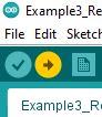
Save the file and click on the Upload button to upload the example onto the Artemis:
Open Tools\Serial Monitor to see the serial messages from the Artemis.
Check that the baud rate is set to 115200:
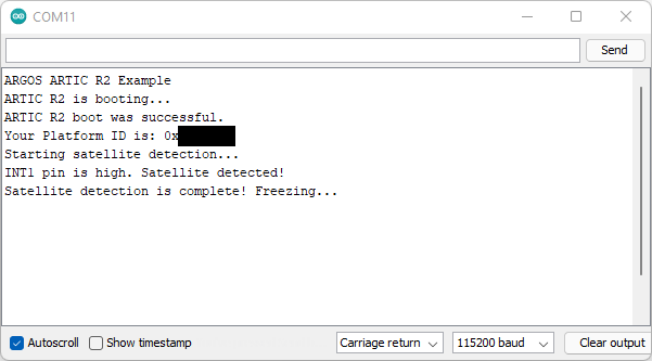
The two red power LEDs and the yellow RX LED on the Satellite Transceiver Shield will light up when the code is running.
Once the ARTIC R2 has booted, the code will read the pre-programmed Platform ID from flash memory. If it does not find one, you will see a message reminding you to install v1.0.9 of the ARTIC R2 library.
The ARTIC R2 will try to detect a satellite for up to 10 minutes. You may wish to log into the ARGOS website and predict when the next satellite pass will take place before running this example.
Current Draw
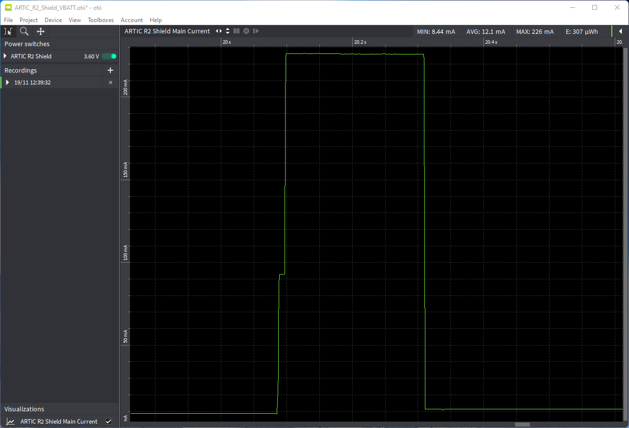
Knowing the current drawn by the ARTIC R2 Shield is of course very important when calculating your battery life.
We measured the ARTIC R2 Shield's current draw using the fantastic Otii Arc Power Analyzer. The Otii Arc was configured to output 3.6V and we connected it to the Shield's VBATT pin to replicate a LiPo battery.
- Current Draw:
- Sleep (PWR EN and RF EN low): 51µA
- Idle (power LEDs enabled): 7.2mA (AVG)
- Receive: 32.9mA
- Transmit (full power, G8 pin high): 226mA
- Transmit (reduced gain, G8 pin low): 170mA
Here is the data captured by Otii Arc when transmitting ARGOS 3 ZE data at full power:
And here is the current draw when transmitting ARGOS 3 ZE data at reduced power:

Certification
The ARGOS ARTIC R2 Satellite Transceiver Shield has been tested and certified by Kinéis, who are responsible for the operation of the ARGOS system. You can find copies of the ARGOS 2, 3 and 4 certificates below.
We are very grateful for the time and effort Kinéis have spent testing the SparkFun ARTIC R2 products.
Troubleshooting
Resources and Going Further
For more information about the ARGOS ARTIC R2 Satellite Transceiver Shield, check out the following links:
ARGOS ARTIC R2 Satellite Transceiver Shield Documentation:
- Schematic
- Eagle Files
- ARGOS Chipset Info Sheet
- ARTIC R2 User Datasheet v1.1
- GitHub Hardware Repo
- Arduino Examples
- SparkFun ARGOS ARTIC R2 Arduino Library
ARGOS ARTIC R2 Documentation: