Ardumoto Kit Hookup Guide
Resources and Going Further
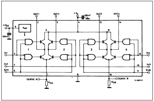
The Ardumoto has been designed primarily to be a motor driver, but we've taken extra time to make sure the L298 IC can be fully controlled, given the user understands the way it works. The datasheet contains a schematic diagram of the internal functions of the IC, which is the first thing to look at and contemplate before trying to do wacky things with your Ardumoto.
As can be seen from the block diagram, the L298 is actually four totem drives with two common grounds, intended for full-bridge motor-driving applications.
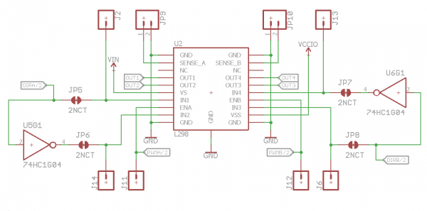
To make the Ardumoto, we've connected the pairs with one of each inverted, to allow a direction control. The enable pin is then PWM'd such that the output goes between drive enabled and high impedance. This allows coasting of the motors when not driven.
Another way the motors could have been hooked up is to PWM the input pins and keep enable high. This would provide motor resistance against movement when not under power, and a PWM value of 1/2 would be "off."
Advanced Pins and Connections
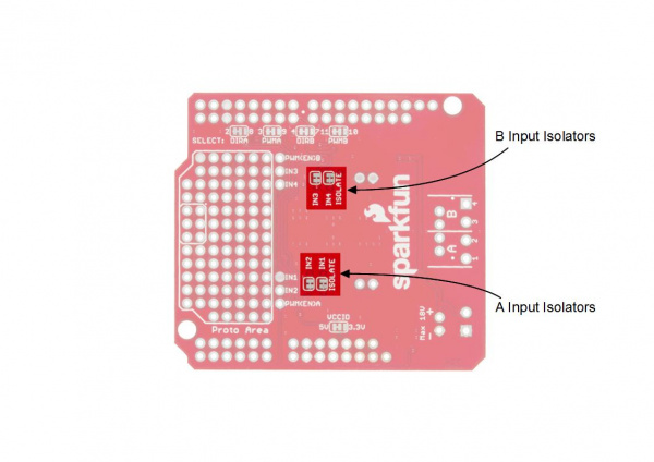
The other jumpers and pins are for flexible configuration. They allow the L298 to be completely isolated from the control lines so that it may be connected in very specific ways, but it's up to you to figure out how to solve the engineering problems you'll face.
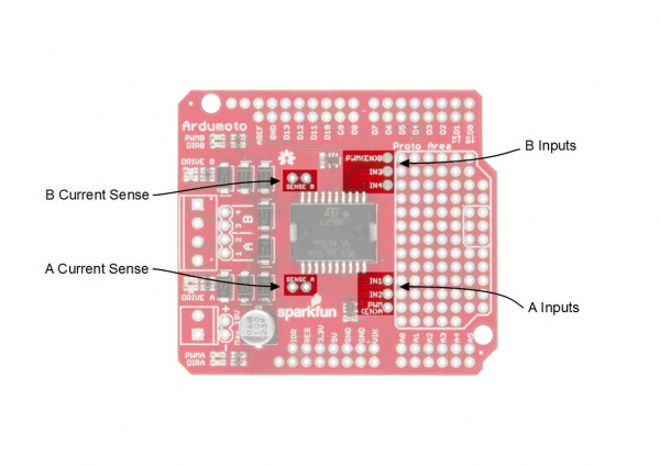
The A/B Isolate jumpers and the A/B inputs work together. If the 'ISOLATE' jumpers are all opened, and the 'SELECT' pins are all opened, the inputs to the L298 are not connected to anything but the six input pins by the proto area. They can then be used however the designer wishes in conjuction with the proto area.
The other curious feature is the pairs of pins labeled 'SENSE'. If you look closely, you'll notice each pair is shorted together, and connected to ground. It is possible to detect current through each motor by cutting the jumper between these pins, supplying a low-ohm resistor and measuring the voltage across it. Not for the faint of heart.
Possible uses:
- Current sense --- break the current sense link between through-holes and insert a 0.05 or 0.1 ohm resistor. Then, use an op-amp to amplify the voltage across the resistor to measure current with an ADC.
- Four independent totem drive circuits using both timer one and timer two.
- Non-coasting drive configuration.
- Bridging output (and control lines) for 4A single drive --- add a heatsink with thermal tape!
Resources
- Ardumoto Shield Schematic --- A PDF of the shield's schematic.
- Ardumoto Shield Github Repository --- The design files and examples.
- L298 Data Sheet --- Everything you could ever want to know about the L298 dual-motor driver.
- Secrets of Arduino PWM -- Gives a good description of low-level timer usage.
- Example Using TimerOne --- This example included with the product repo shows using the motor driver with the TimerOne library.
Going Further
- HUB-ee Buggy Project --- Build your own buggy using an Ardumoto shield.
- Assembly Guide for RedBot --- If you're looking for a complete, beginner-level robotics platform, check out the RedBot Kit. It's Arduino-compatible, and the RedBot Mainboard has a motor driver built into it, so you don't even need an Ardumoto Shield.
- Getting Started with the MiniMoto --- The MiniMoto is a more advanced, digitally controlled, low-voltage DC motor driver. Great if you need a smaller form-factor motor controller.
- How to Power a Project --- Batteries? Wall warts? Solar? If you're not sure how to power your Ardumoto Shield project, take a trip over to this tutorial.


