Ardumoto Kit Hookup Guide
 jimblom,
  MTaylor
Ardumoto Overview
Before you get your soldering iron out, or start attaching motors, it'd be best if we briefly covered the basics of the Ardumoto Shield. On this page, we'll highlight the important inputs and outputs of the shield, so you can get a better idea of how you want to assemble it later.
Pins and Connectors
Here's an annotated view of the shield, highlighting the important pins and components:
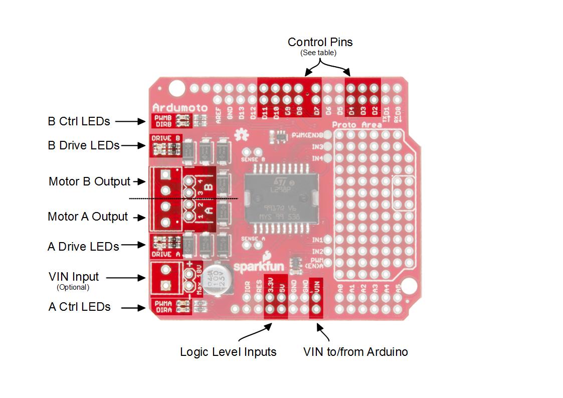
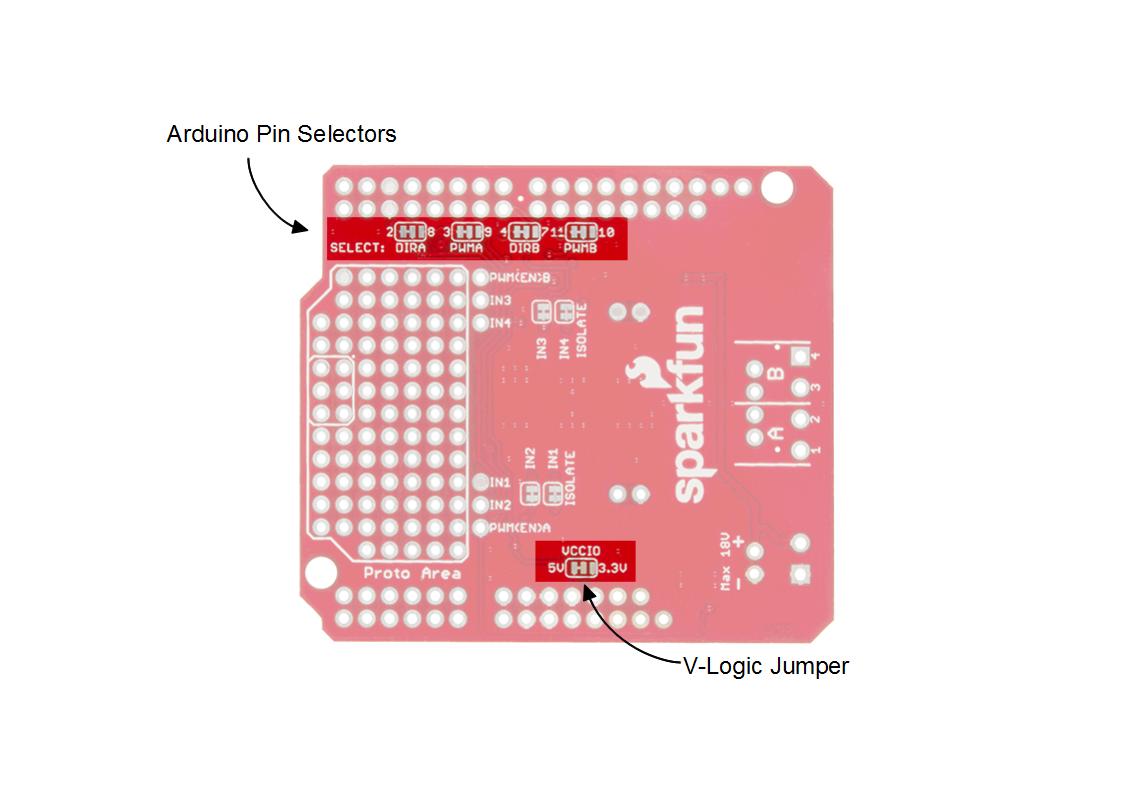
Each motor uses two pins: the digital output for direction and the PWM for speed. The factory configuration uses Arduino pins 2, 3, 4 and 11. The alternate configuration uses pins 7, 8, 9 and 10. If the alternate pins are needed, you'll have to cut the copper links on the bottom and apply solder to bridge to the other selection where necessary. For this guide, just leave everything in the default positions.
If the shield is used on a 3.3V Arduino (such as the Arduino Pro 328 - 3.3V/8MHz), chances are there's no 5V supply, so you'll have to move the VCCIO jumper to the 3.3V side. This jumper selects the voltage for the L298's logic. If you're using an Uno, or 5V 328p of another variety, leave this in the default position.
This table describes the pin function for each configuration.
| Default Pin |
Alternate Pin |
Ardumoto Shield Pin Label | Notes |
|---|---|---|---|
| 2 | 8 | DIR A | A digital signal to control the rotation direction of motor A (e.g., HIGH drives current from output 4 to 3). |
| 3 | 9 | PWM A |
A PWM signal to control the speed of motor B. 0=off, 255=max speed. |
| 4 | 7 | DIR B |
A digital signal to control the rotation direction of motor A (e.g., HIGH drives current from output 2 to 1). |
| 11 | 10 | PWM B |
A PWM signal to control the speed of motor B. 0=off, 255=max speed. |
While the Ardumoto Shield is attached to an Arduino, the used pins shouldn't be connected to anything else.
Motor Outputs
Both of the L298's motor driver outputs are broken out to the edge of the shield. These 2-pin outputs are broken out to two footprints: a 3.5mm-pitch screw terminal and a 0.1"-pitch header. You can use either to wire up your motor, but screw terminals make life much easier if you need to disconnect your motor. The L298 is perfect for building simple two-wheel-drive robot platforms --- connect one motor to port A and the other motor to port B.
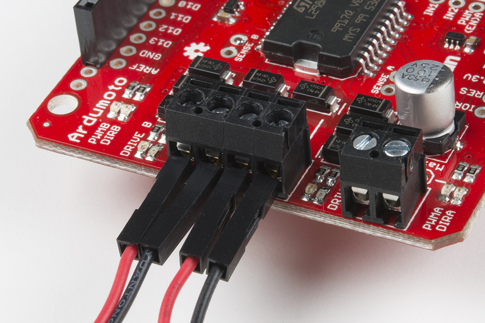
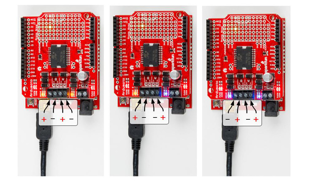
Technically, there is no right or wrong way to connect your motor's wires to the two output pins, but to help keep things straight, we suggest connecting the red / black wire for each motor to pins 1 / 2 on port A and pins 3 / 4 on port B, respectively.
The right and left motors of a robot spin different directions with the same polarity drive because of the orientation. If you want to keep DIR consistently moving that side of the bot "forward," you may end up swapping either the motor leads of one side or the logic in the code, but not both. Play around with the leads of the motors on their respective sides and watch the indicator LEDs to see the effect.
LED Indicators
Next to each of the motor outputs is a pair of blue and yellow LEDs, which indicate the direction your motor is spinning. These are great once you get to debugging your project. They're also useful if you want to test your sketch without wiring up any motors.
There are also four red LEDs (PWMA, DIRA, PWMB, DIRB) that are wired to the control lines directly, showing what your code is doing and also if the pins are configured correctly.
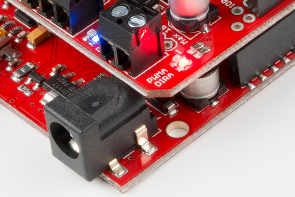
When the DIR LED of a side is illuminated, the driver will allow current from pin 2 to 1, and the blue LED will be lit. Alternately, the yellow LEDs will be lit. With a motor connected, the inductive effects can cause the opposite drive LED to illuminate slightly; this is OK. The blue and yellow LEDs are there to help show what the actual outputs of the driver are doing. Use the red LEDs to debug your code.
Supply Voltage
The Ardumoto Shield should be powered through one of two power supply inputs. Pick one or the other:
- The barrel jack input on the Arduino.
- The VIN input on the shield
If you don't want to use the Arduino's barrel jack input, you can use the VIN input on the shield instead. This voltage input will supply both the shield and the Arduino. Like the motor outputs, this connection is broken out to both a 3.5mm screw terminal and a 0.1"-pitch header.
Do not supply power to both the Arduino barrel jack input and VIN on the shield! Doing this will cause current to flow from one power supply to the other if the voltages are not identical.
Spec'ing a Power Supply
Because VIN powers both your Arduino and your motors, you need to take extra care in deciding what you'll use to power your Arduino/Ardumoto combo. Not only does VIN have to fall within the acceptable range of your Arduino (usually 6--15V), but it also has to meet the specifications of your motor.
Check the voltage and current requirements of your motor before deciding how to power your Ardumoto project. These specifications vary. The 65 RPM Hobby Gearmotors, for example, have a recommended range of 3--6V, but can be safely powered at up to 9V.
We recommend 9V alkaline batteries as an easy, if not very sustainable, option. Dual-cell LiPo battery packs (7.4V nominal, 1,000mAh capacity) are also a good option if you're looking for something mobile. A 9V wall wart can work if your project is stationary. For more help picking a power supply, check out our How to Power a Project tutorial.