MiniMoto DRV8830 Hookup Guide
This Tutorial is Retired!
This tutorial covers concepts or technologies that are no longer current. It's still here for you to read and enjoy, but may not be as useful as our newest tutorials.
 SFUptownMaker
Introduction
SparkFun's MiniMoto board is an I2C-based DC motor driver. It's designed to be used in a system with up to 8 additional MiniMotos, all on the same data lines.
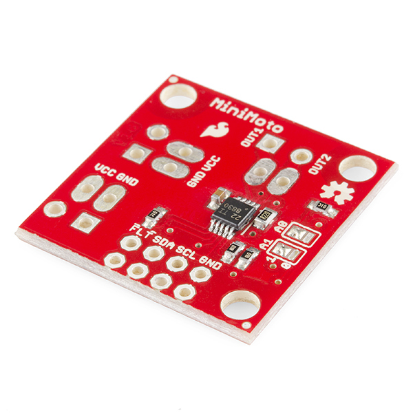
SparkFun MiniMoto Breakout - DRV8830
BOB-11890In addition to the benefit of being controlled via I2C, which frees up data lines and processing on the CPU to be used for other tasks, the MiniMoto has the lowest voltage output capability of any current SparkFun DC motor driver -- 2.7V. This means that low voltage systems running on single-cell LiPo batteries can use the MiniMoto, and low voltage motors (such as those which ship with Tamiya gearbox products) can be used with the MiniMoto.
Before You Begin...
You might want to review some of these documents before you get started, since familiarity with these topics will be assumed for the rest of the tutorial.
- What is an Arduino? - We'll be using the Arduino environment to demonstrate the MiniMoto.
- Installing the Arduino IDE - If you don't have the Arduino software installed, this guide will help you out.
- Installing an Arduino Library - To get the most out of the MiniMoto, you'll want to install our MiniMotolibrary. This tutorial will show you how.
- Pulse width modulation (PWM) - The MiniMoto uses PWM to control the speed of the motors. It's probably a good idea to be familiar with the concept.
- I2C - The MiniMoto uses I2C to communicate with its controlling CPU. While the MiniMoto is accessible through the library with no knowledge of I2C required, if you want to get more out of it, you can check out this tutorial.
Hardware
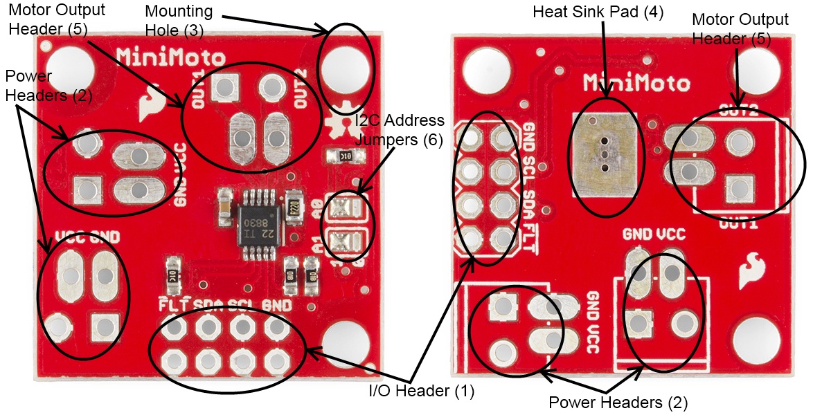
The MiniMoto is a pretty simple board; here's a little walkthrough to get you up-to-speed on its various features.
- I/O header (1) - Two rows of .1" headers provide access to the I2C lines, the FAULT signal, and a ground reference. One row is provided to connect to the controlling CPU; the other can be jumped to the next MiniMoto board. The FAULT line is open-drain, which means that the signal will assert low during a fault condition regardless of the number of MiniMoto boards connected in parallel.
- Power headers (2) - Two power header connections are provided -- one for input and one to pass power through to the next MiniMoto board. There are two sets of pads for each of these: one which is spaced for .1" headers and one spaced for a 3.5mm screw terminal.
- Mounting holes (3) - Three mounting holes are in the corners of the boards; the spacing along the edges is 1" (25mm). The holes are sized for #4-40 screws but a metric M3 should work just as well.
- Bare metal heat sink pad (4) - On the opposite side of the board from the components is a piece of bare copper which is fairly tightly coupled to the power pad on the underside of the drive IC. This pad is sized to fit our small heatsink for improved heat dissipation; you'll need to hold it down with either thermal tape or thermal paste.
- Motor output header (5) - The motor output goes to this header, which has provision for either .1" pins or the same 3.5mm screw terminal used on the power connections.
- I2C address select jumpers (6) - Each board has address selection jumpers that allow the user to set one of 9 addresses. See the next page for explanations of how to set addresses with these jumpers.
Electrical Considerations
The MiniMoto is designed to operate from 2.75V to 6.8V and to drive motors at up to 900mA of current. The minimum logic level required to communicate reliably with the chip varies with the supply voltage: however, at the maximum operating voltage of 6.8V, the minimum the chip will recognize as a high is 3.13V, so a 3.3V input will be recognized comfortably.
The I2C bus can operate at up to 400kHz, depending on the additional load on the bus. While the chip is capable of communications at up to 400kHz, a heavily loaded bus may require that the data rate be dropped to maintain signal integrity. The MiniMoto library operates at 100kHz, which should low enough to work in most conditions.
Arduino Library
In order to make the MiniMoto as easy as possible to use, we've created a simple library for Arduino. Here's the information you'll need to get it working.
Setting the I2C Address
The MiniMoto board has two jumpers for setting its I2C address. The jumpers can be in one of three states: open, 1, or 0. They ship by default in the 1-1 state, which sets an address of 0xD0 for the part.
By adding or removing solder, you can change the address. Here's a little chart explaining the settings.
| A1 | A0 | Address |
|---|---|---|
| 0 | 0 | 0xC0 |
| 0 | open | 0xC2 |
| 0 | 1 | 0xC4 |
| open | 0 | 0xC6 |
| open | open | 0xC8 |
| open | 1 | 0xCA |
| 1 | 0 | 0xCC |
| 1 | open | 0xCE |
| 1 | 1 | 0xD0 |
When you declare an object of MiniMoto class, the only parameter to pass is the address of that board, according to this chart.
Library Functions
The DRV8830 chip on the MiniMoto is a fairly simple chip, having only two registers, and the library is similarly simple.
language:cpp
MiniMoto(byte addr);
This is the class constructor for the MiniMoto class. The addr parameter is the value from the chart above, determined by the jumper settings on the board.
void drive(int speed);
The MiniMoto drives the motor by PWM; the magnitude can range from 6-63. Attempts to set speed lower than 6 will be ignored; speeds higher than 63 will be truncated to 63. The sign of the value determines the direction of the motion.
void stop();
void brake();
Both of these functions will halt the motor's motion; stop() allows the motor to coast to a halt, while brake() basically shorts the motor wires together, presenting a heavy load to the motor and dragging it to a halt quicker. It will also cause the motor to be harder to turn, providing a braking function on slopes or against loads attempting to turn the motor.
byte getFault();
There are several faults which can occur; when a fault occurs, the FAULTn line will be asserted low and the getFault() function can be called to determine the nature of the fault. Calling getFault() clears the fault bit and allows the driver to resume operation, although if the condition which caused the fault still exists, the driver may immediately return to fault status.
To determine the nature of the fault, several constants have been defined:
- FAULT - if FAULT bit is not set, no fault has occurred. This is an important check, as the FAULTn pin can be asserted, and other bits in the return value can be set, without fault conditions existing.
- ILIMIT - the ILIMIT bit will be set if the current limit set by the sense resistor has been violated for more than 275ms. This will not result in the motor driver being disabled.
- OTS - indicates a thermal shutdown event. The output will be disabled, but operation will resume automatically when the die temperature has fallen to safe levels.
- UVLO - undervoltage lockout due to supply voltage dipping below a safe level (~2.5V). Operation will resume when the supply voltage rises to a safe level again (~2.75V).
- OCP - a significant overcurrent event has occurred. This is different to the ILIMIT fault because it is intrinsic to the driver; it generally indicates that the output is shorted or some similar issue. When an OCP error occurs, operation will be suspended until the fault bit is cleared.
Note that it is possible for the FAULTn line to be asserted without a fault having occurred; however, the FAULT bit will always be set if a fault has occurred.
Example
Here's a simple example of an Arduino sketch, using the library to control the two DC motors on a Tamiya twin motor gearbox. We'll take the sketch bit by bit, and explain it as we go.
#include <minimoto.h>  // Include the MiniMoto library

// Create two MiniMoto instances, with different address settings.
MiniMoto motor0(0xCE); // A1 = 1, A0 = clear
MiniMoto motor1(0xD0); // A1 = 1, A0 = 1 (default)
This first section lays the groundwork for the use of the library. In this case, we're using two MiniMoto boards, one with the address jumpers in the default state and one with jumper A0 cleared.
#define FAULTn 16 // Pin used for fault detection.
The FAULTn pin is an open drain output, so any number of MiniMoto boards can be connected to a single input. A pullup resistor is included on the MiniMoto board. Pin 16 corresponds to pin A2.
void setup()
{
  Serial.begin(9600);
  Serial.println("Hello, world!");
  pinMode(FAULTn, INPUT);
}
setup() is pretty simple; initialize the serial port, print a welcome message, and initialize the FAULTn detection pin.
void loop()
{
  Serial.println("Forward!");
  motor0.drive(10);
  motor1.drive(10);
  delayUntil(10000);
  Serial.println("Stop!");
  motor0.stop();
  motor1.stop();
  delay(2000);
  Serial.println("Reverse!");
  motor0.drive(-10);
  motor1.drive(-10);
  delayUntil(10000);
  Serial.println("Brake!");
  motor0.brake();
  motor1.brake();
  delay(2000);
}
loop() turns the motors one way for a bit, then stops or brakes them, then goes the other way for a bit. We'll talk about delayUntil() momentarily; for now, just know that it's a custom function which includes polling for fault conditions.
void delayUntil(unsigned long elapsedTime)
{
  unsigned long startTime = millis();
  while (startTime + elapsedTime > millis())
  {
delayUntil() is a custom replacement for delay() which polls for fault conditions on the MiniMoto boards and reports them if they exist. The delay portion of the function is handled by this while() loop; for more information on how that works, see the built-in Arduino example "BlinkWithoutDelay".
    if (digitalRead(FAULTn) == LOW)
    {
Our first-level check for faults is done by watching the FAULTn pin. We could skip this and go directly to polling the devices by calling getFault() for each one; this is faster, but requires the use of an additional IO pin.
byte result = motor0.getFault();
The return value from getFault() is nothing more than the contents of register 0x01 of the DRV8830. We abstract it a bit to make this easier for the user, who doesn't have to care about registers and things like that to use this part.
      if (result & FAULT)
      {
This is where we definitively detect whether a fault has occurred or not. It is possible (and indeed, not uncommon) for the FAULTn pin to go low without a fault actually having occurred. The FAULT constant is a single bit (bit 0, in fact) which, if set, indicates that a fault condition has actually occurred. If the result of an AND of that constant with the result from getFault() is non-zero, we know that bit is set and can then proceed to identify which fault bit is set.
        Serial.print("Motor 0 fault: ");
        if (result & OCP) Serial.println("Chip overcurrent!");
        if (result & ILIMIT) Serial.println("Load current limit!");
        if (result & UVLO) Serial.println("Undervoltage!");
        if (result & OTS) Serial.println("Over temp!");
        break;
      }
We use the same method (ANDing the result with a single-bit constant) to determine which of the bits in the fault register was set, then we report that to the user via the serial port. Since a fault occurred, we want to bail out of the loop, so we include a break statement.
      result = motor1.getFault();
      if (result & FAULT)
      {
        Serial.print("Motor 1 fault: ");
        if (result & OCP) Serial.println("Chip overcurrent!");
        if (result & ILIMIT) Serial.println("Load current limit!");
        if (result & UVLO) Serial.println("Undervoltage!");
        if (result & OTS) Serial.println("Over temp!");
        break;
      }
    }
  }
}
Repeat for the second motor.
This example code is included with the library, and the library can be found by downloading the zip file of the product GitHub repository.
Resources and Going Further
With that, you should have all the knowledge to get your motors up and spinning. Here are some other resources to explore.
Here are some other motor related products and hookup guides for you to check out.