Arduino Weather Shield Hookup Guide V12
 Nate, santaimpersonator,
  SparkFro
Example Firmware - Weather Station with GPS
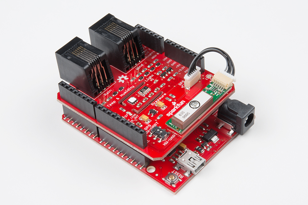
Attach the GP-735 GPS module using a JST cable. To secure the module, there is space on the shield to attach the module using double-stick tape.
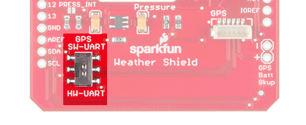
There is a switch labeled Serial on the shield. This is to select which pins on the Arduino to connect the GPS to. In almost all cases the switch should be set to 'Soft'. This will attach the GPS serial pins to digital pins 5 (TX from the GPS) and 4 (RX into the GPS).
Grab the GPS example sketch from the GitHub repo that demonstrates using the GP-735 with all the other sensors. Load it onto your Arduino, and open the serial monitor at 115200 bps.
You can also copy the code below:
language:c
/*
  Weather Shield Example
  By: Nathan Seidle
  SparkFun Electronics
  Date: November 16th, 2013
  License: This code is public domain but you buy me a beer if you use this and we meet someday (Beerware license).

  Much of this is based on Mike Grusin's USB Weather Board code: https://www.sparkfun.com/products/10586

  This code reads all the various sensors (wind speed, direction, rain gauge, humidity, pressure, light, batt_lvl, GPS data)
  and reports it over the serial comm port. This can be easily routed to a datalogger (such as OpenLog) or
  a wireless transmitter (such as Electric Imp).

  Measurements are reported once a second. The windspeed and rain gauge are tied to interrupts and are
  calculated at the instance of each report.

  This example code assumes the GP-735 GPS module is attached.

  Updated by Joel Bartlett
  03/02/2017
  Removed HTU21D code and replaced with Si7021

  Updated be Wes Furuya
  06/19/2023
  Implemented "Weather Meter" Arduino library
  Updated to TinyGPSPlus Arduino library
*/

#include <Wire.h>                                        //I2C needed for sensors
#include "SparkFunMPL3115A2.h"                           //Pressure sensor - Search "SparkFun MPL3115" and install from Library Manager
#include "SparkFun_Si7021_Breakout_Library.h"            //Humidity sensor - Search "SparkFun Si7021" and install from Library Manager
#include "SparkFun_Weather_Meter_Kit_Arduino_Library.h"  //Weather meter kit - Search "SparkFun Weather Meter" and install from Library Manager
#include <SoftwareSerial.h>                              //Needed for GPS
#include <TinyGPSPlus.h>                                 //Parsing GPS data - Available through the Library Manager.


//Hardware pin definitions
//-=-=-=-=-=-=-=-=-=-=-=-=-=-=-=-=-=-=-=-=-=-=-=-=-=-=-=-=
// digital I/O pins
const byte WSPEED = 3;
const byte RAIN = 2;
const byte STAT1 = 7;
const byte STAT2 = 8;
// const byte GPS_PWRCTL = 6;              //Pulling this pin low puts GPS to sleep but maintains RTC and RAM
static const int RXPin = 5, TXPin = 4;  //GPS is attached to pin 4(TX from GPS) and pin 5(RX into GPS)
static const uint32_t GPSBaud = 9600;   // Default baud rate of the GP-735 GPS module


// analog I/O pins
const byte REFERENCE_3V3 = A3;
const byte LIGHT = A1;
const byte BATT = A2;
const byte WDIR = A0;
//-=-=-=-=-=-=-=-=-=-=-=-=-=-=-=-=-=-=-=-=-=-=-=-=-=-=-=-=

//Global Variables
//-=-=-=-=-=-=-=-=-=-=-=-=-=-=-=-=-=-=-=-=-=-=-=-=-=-=-=-=
long lastSecond;     //The millis counter to see when a second rolls by
long lastChars = 0;  //Character counter for GPS parsing

float humidity = 0;  // [%]
float tempf = 0;     // [temperature F]
//float baromin = 30.03;// [barom in] - It's hard to calculate barom in locally, do this in the agent
float pressure = 0;

float wind_dir = 0;    // [degrees (Cardinal)]
float wind_speed = 0;  // [kph]
float rain = 0;        // [mm]

float batt_lvl = 11.8;  //[analog value from 0 to 1023]
float light_lvl = 455;  //[analog value from 0 to 1023]
//-=-=-=-=-=-=-=-=-=-=-=-=-=-=-=-=-=-=-=-=-=-=-=-=-=-=-=-=


MPL3115A2 myPressure;                                      //Create an instance of the pressure sensor
Weather myHumidity;                                        //Create an instance of the humidity sensor
SFEWeatherMeterKit myweatherMeterKit(WDIR, WSPEED, RAIN);  // Create an instance of the weather meter kit

TinyGPSPlus gps;
SoftwareSerial ss(RXPin, TXPin);


void setup() {
  Serial.begin(115200);
  ss.begin(GPSBaud);

  Serial.println("Weather Shield Example");

  pinMode(STAT1, OUTPUT);  //Status LED Blue
  pinMode(STAT2, OUTPUT);  //Status LED Green

  // pinMode(GPS_PWRCTL, OUTPUT);
  // digitalWrite(GPS_PWRCTL, HIGH);  //Pulling this pin low puts GPS to sleep but maintains RTC and RAM

  pinMode(REFERENCE_3V3, INPUT);
  pinMode(LIGHT, INPUT);

  //Configure the pressure sensor
  myPressure.begin();               // Get sensor online
  myPressure.setModeBarometer();    // Measure pressure in Pascals from 20 to 110 kPa
  myPressure.setOversampleRate(7);  // Set Oversample to the recommended 128
  myPressure.enableEventFlags();    // Enable all three pressure and temp event flags

  //Configure the humidity sensor
  myHumidity.begin();

  // The weather meter kit library assumes a 12-bit ADC
  // Configuring a 10-bit ADC resolution for the ATmega328 (RedBoard/Uno)
  myweatherMeterKit.setADCResolutionBits(10);

  // Begin weather meter kit
  myweatherMeterKit.begin();

  lastSecond = millis();

  Serial.println("Weather Shield online!");
}

void loop() {
  //Keep track of which minute it is
  if (millis() - lastSecond >= 1000) {
    lastSecond += 1000;
    //Report all readings every second
    printWeather();

    // Report GPS Data
    printGPS();

    Serial.print(",");
    Serial.println("#");
  }

}


void printGPS() {
  lastChars = gps.charsProcessed();

  while (millis() - lastSecond < 900) {
    //If data is available, parse out the information
    if (ss.available() > 0) {
      gps.encode(ss.read());

      // Check if GPS data was updated
      if (gps.location.isUpdated() && gps.date.isUpdated() && gps.time.isUpdated()) {
        digitalWrite(STAT2, HIGH);  //Turn on stat LED (Green)

        // Check if all data is valid
        // if (gps.location.isValid() && gps.date.isValid() && gps.time.isValid()) {
        //   digitalWrite(STAT2, HIGH);  //Turn on stat LED (Green)
        // }

        break;
      }

      else {
        digitalWrite(STAT2, LOW);  //Turn off stat LED
      }
    }
  }

  //Prints error message if not data has been receiver from the GPS module
  if (gps.charsProcessed() - lastChars < 10) {
    Serial.println();
    Serial.println(F("No GPS data: check wiring/switch."));
    digitalWrite(STAT2, LOW);  //Turn off stat LED
  }

  parseGPS();
}


void parseGPS() {

  if (gps.location.isValid()) {
    Serial.print(", lat=");
    Serial.print(gps.location.lat(), 6);
    Serial.print(", lng=");
    Serial.print(gps.location.lng(), 6);
    Serial.print(", altitude=");
    Serial.print(gps.altitude.meters());
    Serial.print(", sats=");
    Serial.print(gps.satellites.value());
  } else {
    Serial.print(F(", Location=INVALID"));
  }

  Serial.print(", date=");
  if (gps.date.isValid()) {
    Serial.print(gps.date.month());
    Serial.print(F("/"));
    Serial.print(gps.date.day());
    Serial.print(F("/"));
    Serial.print(gps.date.year());
  } else {
    Serial.print(F("INVALID"));
  }

  Serial.print(", time=");
  if (gps.time.isValid()) {
    if (gps.time.hour() < 10) Serial.print(F("0"));
    Serial.print(gps.time.hour());
    Serial.print(F(":"));
    if (gps.time.minute() < 10) Serial.print(F("0"));
    Serial.print(gps.time.minute());
    Serial.print(F(":"));
    if (gps.time.second() < 10) Serial.print(F("0"));
    Serial.print(gps.time.second());
    Serial.print(F("."));
    if (gps.time.centisecond() < 10) Serial.print(F("0"));
    Serial.print(gps.time.centisecond());
    Serial.print(" (GMT)");
  } else {
    Serial.print(F("INVALID"));
  }
}

//Calculates each of the weather variables
void calcWeather() {

  //Calc temp/humidity from Si7021 sensor
  humidity = myHumidity.getRH();
  tempf = myHumidity.readTempF();

  //Weather Meter Kit
  //Calc Wind
  wind_dir = myweatherMeterKit.getWindDirection();
  wind_speed = myweatherMeterKit.getWindSpeed();
  //Calc Rain
  rain = myweatherMeterKit.getTotalRainfall();

  //Calc pressure from MPL3115A2
  pressure = myPressure.readPressure();

  //Calc light level
  light_lvl = get_light_level();

  //Calc battery level
  batt_lvl = get_battery_level();
}

//Returns the voltage of the light sensor based on the 3.3V rail
//This allows us to ignore what VCC might be (an Arduino plugged into USB has VCC of 4.5 to 5.2V)
float get_light_level() {
  float operatingVoltage = analogRead(REFERENCE_3V3);

  float lightSensor = analogRead(LIGHT);

  operatingVoltage = 3.3 / operatingVoltage;  //The reference voltage is 3.3V

  lightSensor = operatingVoltage * lightSensor;

  return (lightSensor);
}

//Returns the voltage of the raw pin based on the 3.3V rail
//This allows us to ignore what VCC might be (an Arduino plugged into USB has VCC of 4.5 to 5.2V)
//Battery level is connected to the RAW pin on Arduino and is fed through two 5% resistors:
//3.9K on the high side (R1), and 1K on the low side (R2)
float get_battery_level() {
  float operatingVoltage = analogRead(REFERENCE_3V3);

  float rawVoltage = analogRead(BATT);

  operatingVoltage = 3.30 / operatingVoltage;  //The reference voltage is 3.3V

  rawVoltage = operatingVoltage * rawVoltage;  //Convert the 0 to 1023 int to actual voltage on BATT pin

  rawVoltage *= 4.90;  //(3.9k+1k)/1k - multiple BATT voltage by the voltage divider to get actual system voltage

  return (rawVoltage);
}


//Prints the weather variables directly to the port
//I don't like the way this function is written but Arduino doesn't support floats under sprintf
void printWeather() {
  calcWeather();  //Go calc all the various sensors

  digitalWrite(STAT1, HIGH);  //Blink stat LED (Blue)

  Serial.println();
  Serial.print("humidity=");
  Serial.print(humidity, 1);
  Serial.print(" %RH, tempf=");
  Serial.print(tempf, 1);
  Serial.print(" F, pressure=");
  Serial.print(pressure, 2);
  Serial.print(" Pa, wind direction= ");
  Serial.print(wind_dir, 1);
  Serial.print(" deg, wind speed= ");
  Serial.print(wind_speed, 1);
  Serial.print(" kph, total rain= ");
  Serial.println(rain, 1);
  Serial.print(" mm, batt_lvl=");
  Serial.print(batt_lvl, 2);
  Serial.print(" V, light_lvl=");
  Serial.print(light_lvl, 2);

  digitalWrite(STAT1, LOW);  //Blink stat LED
}
You should see output similar to the following:
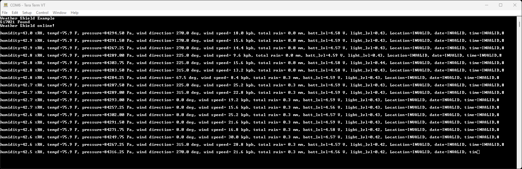
Note: The batt_lvl is indicating 4.08V. This is correct and is the actual voltage read from the Arduino powered over USB. The GPS module will add 50-80mA to the overall power consumption. If you are using a long or thin USB cable you may see significant voltage drop similar to this example. There is absolutely no harm in this! The Weather Shield runs at 3.3V and the Arduino will continue to run just fine down to about 3V. The reading is very helpful for monitoring your power source (USB, battery, solar, etc).
This example demonstrates how you can get location, altitude, and time from the GPS module. This would be helpful with weather stations that are moving such as balloon satellites, AVL, package tracking, and even static stations where you need to know precise altitude or timestamps.