APDS-9960 RGB and Gesture Sensor Hookup Guide
Contributors:
 Shawn Hymel
Shawn Hymel 
Hardware Hookup
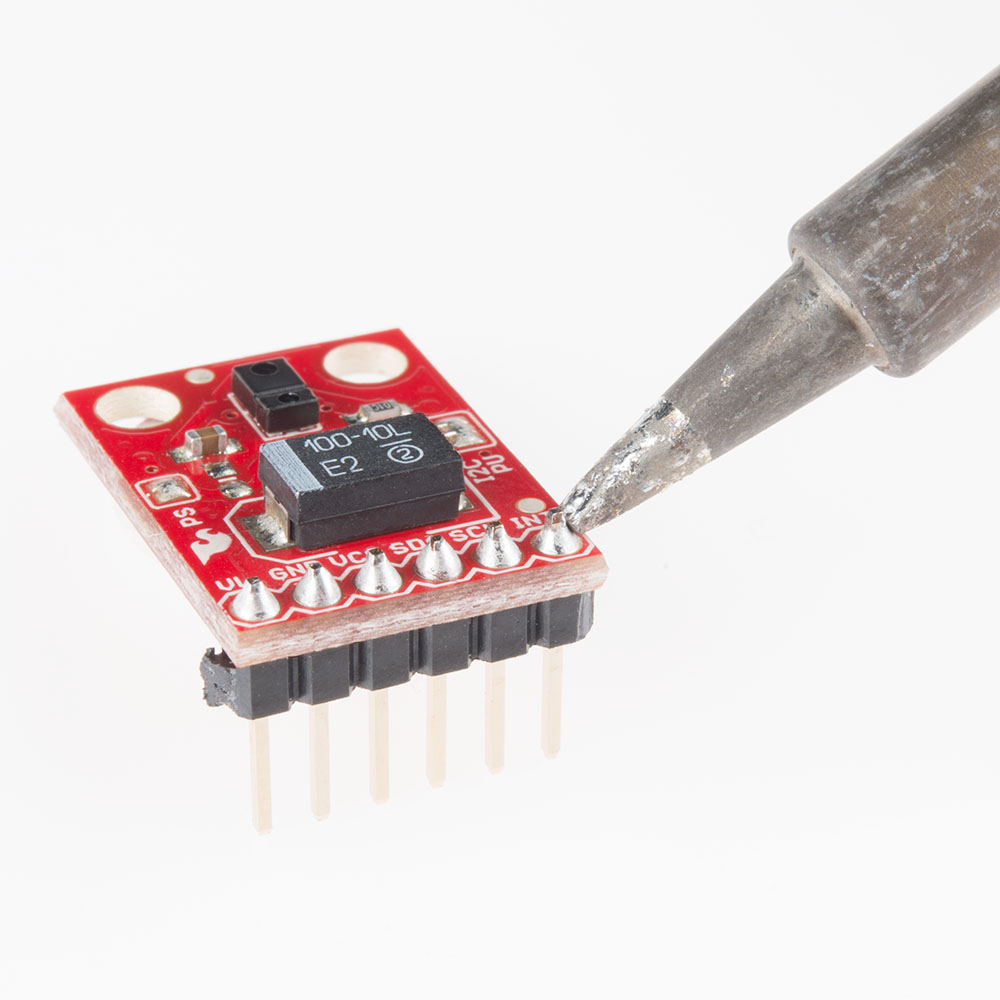
Add Headers
Solder a row of break away male headers to the 6 headers holes on the board.
Connect the Breakout Board
We will be using the Arduino Pro's regulated 3.3V power and I2C bus with the APDS-9960. Note that we are leaving VL on the breakout board unconnected.
IMPORTANT: You must use 3.3V! If you try to use a 5V power supply or 5V I2C communications, you risk damaging the APDS-9960. If you are using a 5V Arduino (e.g. UNO), then you need to have some kind of level shifting.
Connect the breakout board to the following pins on the Arduino:
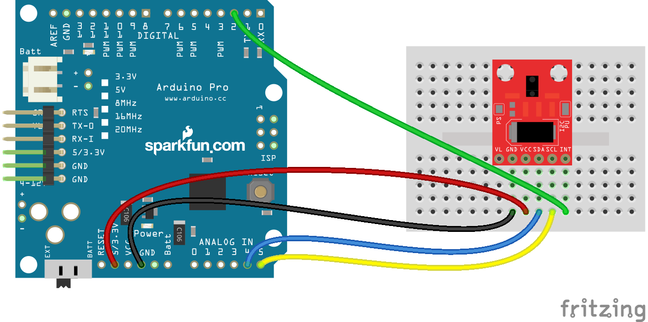
| APDS-9960 Breakout Board | Arduino Pro 3.3V |
|---|---|
| GND | GND |
| VCC | VCC |
| SDA | A4 |
| SCL | A5 |
| INT | 2 |