APDS-9960 RGB and Gesture Sensor Hookup Guide
Contributors:
 Shawn Hymel
Shawn Hymel 
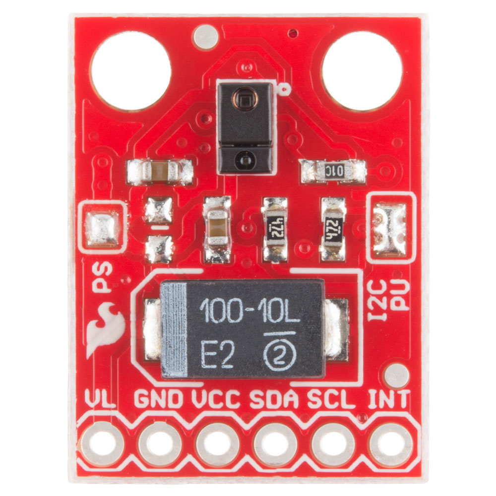
Board Overview
Pin Descriptions
The APDS-9960 breakout board provides 6 pins to provide power to the sensor and I2C bus.
| Pin Label | Description |
|---|---|
| VL | Optional power to the IR LED if PS jumper is disconnected. Must be 3.0 - 4.5V |
| GND | Connect to ground. |
| VCC | Used to power the APDS-9960 sensor. Must be 2.4 - 3.6V |
| SDA | I2C data |
| SCL | I2C clock |
| INT | External interrupt pin. Active LOW on interrupt event |
Setting the Jumpers
On the front of the breakout board are 2 solder jumpers:
- PS -- This jumper connects the power supplies of the sensor and IR LED (also located on the APDS-9960) together. When the jumper is closed (i.e. connected), you only need to supply power to the VCC pin to power both the sensor and the IR LED. If the jumper is open, you need to provide power to both the VCC (2.4 - 3.6V) and VL (3.0 - 4.5V) pins separately. This jumper is closed by default.
- I2C PU -- This is a 3-way solder jumper that is used to connect and disconnect the I2C pullup resistors. By default, this jumper is closed, which means that both SDA and SCL lines have connected pullup resistors on the breakout board. Use some solder wick to open the jumper if you do not need the pullup resistors (e.g. you have pullup resistors that are located on the I2C bus somewhere else).