Adding More SERCOM Ports for SAMD Boards
 M-Short
 Introduction
SERCOM (Serial Communication) is a multiplexed serial configuration used on the SAMD21, SAMD51 and other boards. It allows you to select various serial functions for most of your pins. For example, the ATmega328 which has UART (RX/TX) on one pair of pins, I2C (SDA/SCL) on another set, and SPI (MOSI, MISO, SCK) on another set. The SAMD21 has 5 different internal ports which you can configure to use any combination of UART, I2C, and SPI. The SAMD21 and SAMD51 boards are becoming increasingly popular in part because of this feature. But how do you do it?
Required Materials
To follow along with this tutorial, you will need the following materials. You may not need everything though depending on what you have. Add it to your cart, read through the guide, and adjust the cart as necessary.
ARM-Based Microcontroller
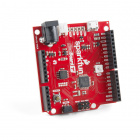
For this tutorial we are going to use the RedBoard Turbo, but you should be able to follow along just fine with any of the SAMD21 boards below (or any not listed below).
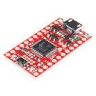
SparkFun SAMD21 Development Breakout
DEV-13672Serial Device and Prototyping Hardware
You'll also need a serial device. We will also be using a 16x2 Serial LCD Screen for our examples since it will accept commands over UART, SPI or I2C. You will need a way to connect your board to the screen as well, but those are the only components needed to follow along.


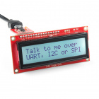
SparkFun 16x2 SerLCD - Black on RGB 3.3V
LCD-14072Tools
Depending on your setup, you may need a soldering iron, solder, general soldering accessories for boards without headers.


Suggested Reading
If you aren’t familiar with the following concepts, we recommend checking out these tutorials before continuing.
SAMD21 Mini/Dev Breakout Hookup Guide
AVR-Based Serial Enabled LCDs Hookup Guide
RedBoard Turbo Hookup Guide
A Look at the RedBoard Turbo
Whenever a new board is added to the Arduino IDE it comes with a couple of variants files (variant.h and variant.cpp). These files define which pins are being used for what. They define where D0 maps to, where the BUILT_IN_LED goes, and which pins are assigned to things like UART, I2C, etc. Pretty much any of the SAMD21 or SAMD51 boards you come across should already have at least 1 UART, I2C, and SPI port defined in their variants file. It is usually easiest to just use those. But once in a while you will want to add another port. For example, you have an accelerometer that you want to use to measure vibrations on 2 different platforms. But the accelerometer only has one available I2C address. While you could use an I2C mux, you can also just add a second I2C port to your board.
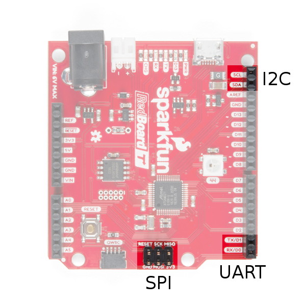
Let's take a look at the RedBoard Turbo. As you can see there is an I2C port broken out at the top right. At the bottom, you'll also see the UART broken out and the pins labeled TX and RX. Finally, you'll see what is often referred to as the legacy ISP header. Originally, this SPI port was tied to one on the side of the board (the ATMega boards only had 1 SPI port) and was used to program the bootloader onto the board. Because a lot of shields use this as the primary SPI port, this is broken out as well. However, they are located a different SPI port than the one on the side for the RedBoard Turbo.
Now let's take a closer look at the SAMD21 and start defining some terms.
- Serial -- Serial communication means one item or bit is sent at a time. This is in contrast to Parallel where multiple items are sent at once on different lines. UART, SPI, and I2C are all types of serial communication.
- UART (Universal Asynchronous Receiver/Transmitter) -- This is what is commonly referred to as serial even though it is only one type of serial. With a TX (transmit) and RX (receive) line this communication protocol does not have a clock line. Also remember that what one device is transmiting the other device is receiving so you will want to connect your TX to RX and RX to TX.
- RX -- Receive line of a UART communication.
- TX -- Transmit line of a UART communication.
- SPI (Serial Peripheral Interface) -- This serial bus has both a line for the master to send data out and the slave to receive (MOSI), one for the slave to send and the master to receive (MISO), and a clock (SCK). The CS line is used to select which board is being talked to. In other words, a bus will have 3+n wires. When a slave's CS line is selected, it knows the master is trying to talk to it. Because this is just a select line, it may or may not be included in a hardware serial interface.
- MOSI -- The master out, slave in line of an SPI bus.
- MISO -- The master in, slave out line of an SPI bus.
- SCK -- The clock line of an SPI bus.
- CS -- The cable select line of an SPI bus. Also, called slave select (SS).
- I2C (or I2C, Inter-Integrated Circuit) -- This is a 2 wire serial interface that uses a clock and data line to pass information. Each device on the bus has a different address which the master will specifiy during communication. I2C buses require pull-up resistors on both lines. Most SparkFun I2C boards have the pull-up resistors built in as well as a solder jumper to disable them.
- SDA -- This is the data line of an I2C bus.
- SCL -- This is the clock line of an I2C bus.
- SERCOM (Serial Communications) -- This is a the name of a serial communications port on the SAMD21 boards. Because of the SAMD21's pin multiplexing, each pin on the chip has multiple function. Therefore, each SERCOM port can use various pins.
- Port
- SERCOM Port -- The SAMD21 has 6 Serial Communication modules what can be configured in various ways. A port or module refers to one of them. This gives us 6 different communications options. Most of the SAMD21 boards use 4-5 of these to bring you 1 SPI, UART, and I2C bus and often use 1 or 2 more for a second SPI, and/or connecting to another chip on the board such as onboard flash or a WiFi module.
- Pad -- Each SERCOM Port will have 4 pads (0-4). In order to determine how to use a SERCOM port, we will need to figure out which pins are on which pads of our port. This is written in a variety of ways, for example pad 0 on SERCOM 1 may be written as SERCOM1/Pad[0], SERCOM1.0, or even 1:0.
- SAMD21 Port -- While Arduino gives names to all usable pins (often based on how they are configured) the chip manufacture does not assign pin numbers in such a way. Instead each pin has a port name. In the case of the SAMD21, the port names will have a letter (either A or B) and a number and look like this: PortA10, PortB08. Often for the sake of room, the Port will be abbreviated to the letter 'P' and the names will look like this: PA10, PB08, etc.
- Macro -- This is a predefined value in your code. Usually designated by the
#definecommand. When looking at board definitions, you will see a lot of macros that have definitions defined elsewhere. The definitions are not as important and understanding what the macro is filling in for. For example, the macroPIN_WIRE_SDAis being used to define which pin you are using for SDA on a Wire (I2C) interface. - Multiplex (or mux for short) -- This is the practice of assigning many conflicting attributes to 1 item and being able to select which one you want. In this case, each pin on the SAMD21 chip is assigned many functions from analog inputs, to digital inputs, to timers, to various SERCOM ports. As we set up a SERCOM port we will need to spend some time selecting the correct feature in our mux.
- Qwiic -- Qwiic is SparkFun's I2C interface. Get it, QwIIC! This port connects to a board I2C port as well as providing power (3.3V). You will see it on quite a few boards including the Redboard Turbo. This is hard wired into the board's SDA and SCL pins so you can't change it.