Adding More SERCOM Ports for SAMD Boards
 M-Short
Datasheets - SAMD21
Graphical Datasheet
Part of the trick of setting up SERCOM Ports is determining which pins go together. You can't just assign them Willy Nilly. The SparkFun graphical datasheets do a pretty good job of summarizing them. We are going to start by looking at the Redboard Turbo and checking its graphical datasheet as well as the SAMD21 datasheet.
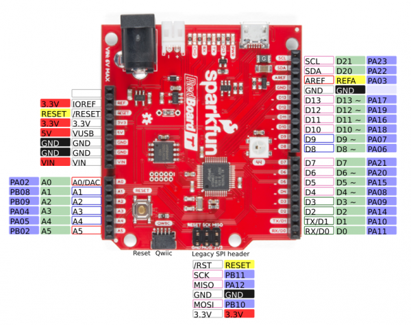
The SparkFun graphical datasheets are great at giving you a quick one page overview of the features of your board. Above you see a simplified version of the Graphical Datasheet for the Redboard Turbo. As you can see the Turbo has 1x Serial port, 1x I2C port (which is also connected to the Qwiic connector) and 1x SPI ports (the legacy ISCP header).
SAMD21 Datasheet
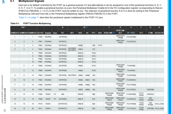
Looking at the SAMD21 datasheet (page 21) under I/O Multiplexing and Considerations, we can start to see all the options each pin can have. We can select any of the columns for each pin. Specifically, we are looking at columns C and D. Also, it is worth noting that the chip on the Redboard Turbo is the SAMD21G18. As you can see there are other SAMD21 chip variants that have more or less pins. The 'G' version is the one we want. As you can see, many of the pins have a 1 or 2 SERCOM ports available.
But What Pin Corresponds Where?
While you can check the schematic/board file to see what pin on the chip goes where, the best option is probably the variant.cpp file for your board. Let's look at this file defined for the RedBoard Turbo. The file starts with a pretty large comment. While this is a good reference, keep in mind that people may choose not to update the comment for their board. Under the comment, you should see the Pin Descriptions. On the RedBoard Turbo, the pin definitions are broken out into sections to make it easier to read. The first section is D0-D13 staring with D0 and D1 which are the UART pins. You'll notice that the first arguments list the port and the pin on that port. The comment at the end also tells you what SERCOM port is being used. If we scroll through and find the pins that are using SERCOM pins, we'll find the following.
language:c
// 0..13 - Digital pins
// ----------------------
// 0/1 - SERCOM/UART (Serial1)
{ PORTA, 11, PIO_SERCOM, (PIN_ATTR_DIGITAL), No_ADC_Channel, NOT_ON_PWM, NOT_ON_TIMER, EXTERNAL_INT_11 }, // RX: SERCOM0/PAD[3]
{ PORTA, 10, PIO_SERCOM, (PIN_ATTR_DIGITAL), No_ADC_Channel, NOT_ON_PWM, NOT_ON_TIMER, EXTERNAL_INT_10 }, // TX: SERCOM0/PAD[2]

// 20..21 I2C pins (SDA/SCL and also EDBG:SDA/SCL)
// ----------------------
{ PORTA, 22, PIO_SERCOM, PIN_ATTR_DIGITAL, No_ADC_Channel, NOT_ON_PWM, NOT_ON_TIMER, EXTERNAL_INT_6 }, // SDA: SERCOM3/PAD[0]
{ PORTA, 23, PIO_SERCOM, PIN_ATTR_DIGITAL, No_ADC_Channel, NOT_ON_PWM, NOT_ON_TIMER, EXTERNAL_INT_7 }, // SCL: SERCOM3/PAD[1]

// 22..24 - SPI pins (ICSP:MISO,SCK,MOSI)
// ----------------------
{ PORTA, 12, PIO_SERCOM_ALT, PIN_ATTR_DIGITAL, No_ADC_Channel, NOT_ON_PWM, NOT_ON_TIMER, EXTERNAL_INT_12 }, // MISO: SERCOM4/PAD[0]
{ PORTB, 10, PIO_SERCOM_ALT, PIN_ATTR_DIGITAL, No_ADC_Channel, NOT_ON_PWM, NOT_ON_TIMER, EXTERNAL_INT_10 }, // MOSI: SERCOM4/PAD[2]
{ PORTB, 11, PIO_SERCOM_ALT, PIN_ATTR_DIGITAL, No_ADC_Channel, NOT_ON_PWM, NOT_ON_TIMER, EXTERNAL_INT_11 }, // SCK: SERCOM4/PAD[3]

// 30..41 - Extra Pins
// ----------------------
// 30/31 - Extra UART
{ PORTB, 22, PIO_SERCOM_ALT, PIN_ATTR_NONE, No_ADC_Channel, NOT_ON_PWM, NOT_ON_TIMER, EXTERNAL_INT_NONE }, // 30/TX: SERCOM5/PAD[2]
{ PORTB, 23, PIO_SERCOM_ALT, PIN_ATTR_NONE, No_ADC_Channel, NOT_ON_PWM, NOT_ON_TIMER, EXTERNAL_INT_NONE }, // 31/RX: SERCOM5/PAD[3]

// 32/33 I2C (SDA/SCL and also EDBG:SDA/SCL)
{ PORTA, 22, PIO_SERCOM, PIN_ATTR_NONE, No_ADC_Channel, NOT_ON_PWM, NOT_ON_TIMER, EXTERNAL_INT_NONE }, // SDA: SERCOM3/PAD[0]
{ PORTA, 23, PIO_SERCOM, PIN_ATTR_NONE, No_ADC_Channel, NOT_ON_PWM, NOT_ON_TIMER, EXTERNAL_INT_NONE }, // SCL: SERCOM3/PAD[1]

// 34..37 - EDBG/SPI
{ PORTA, 19, PIO_SERCOM, PIN_ATTR_NONE, No_ADC_Channel, NOT_ON_PWM, NOT_ON_TIMER, EXTERNAL_INT_NONE }, // D12/MISO: SERCOM1/PAD[3]
{ PORTA, 16, PIO_SERCOM, PIN_ATTR_NONE, No_ADC_Channel, NOT_ON_PWM, NOT_ON_TIMER, EXTERNAL_INT_NONE }, // D11/MOSI: SERCOM1/PAD[0]
{ PORTA, 18, PIO_SERCOM, PIN_ATTR_NONE, No_ADC_Channel, NOT_ON_PWM, NOT_ON_TIMER, EXTERNAL_INT_NONE }, // D10/SS: SERCOM1/PAD[2]
{ PORTA, 17, PIO_SERCOM, PIN_ATTR_NONE, No_ADC_Channel, NOT_ON_PWM, NOT_ON_TIMER, EXTERNAL_INT_NONE }, // D13/SCK: SERCOM1/PAD[1]
Based on the code it looks like we are using SERCOM 0, 1, 3, 4, and 5. Any extra ports we use are going to have to use either SERCOM ports that are not already used or reuse one that is. Also, keep in mind that often unused ports are not removed. For example, this file lists D30 and D31 as an extra serial UART port. But, the board doesn't breakout D30 and D31 (but the SAMD21 development board did) so SERCOM 5 is actually free as well.