Actobotics Basic Differential Platform
 Improvised Dynamics
Hardware Assembly
Ball Casters
The first assembly is the Tamiya Ball caster. Follow the included instructions for the 37mm layout.
Drive Axle Assembly
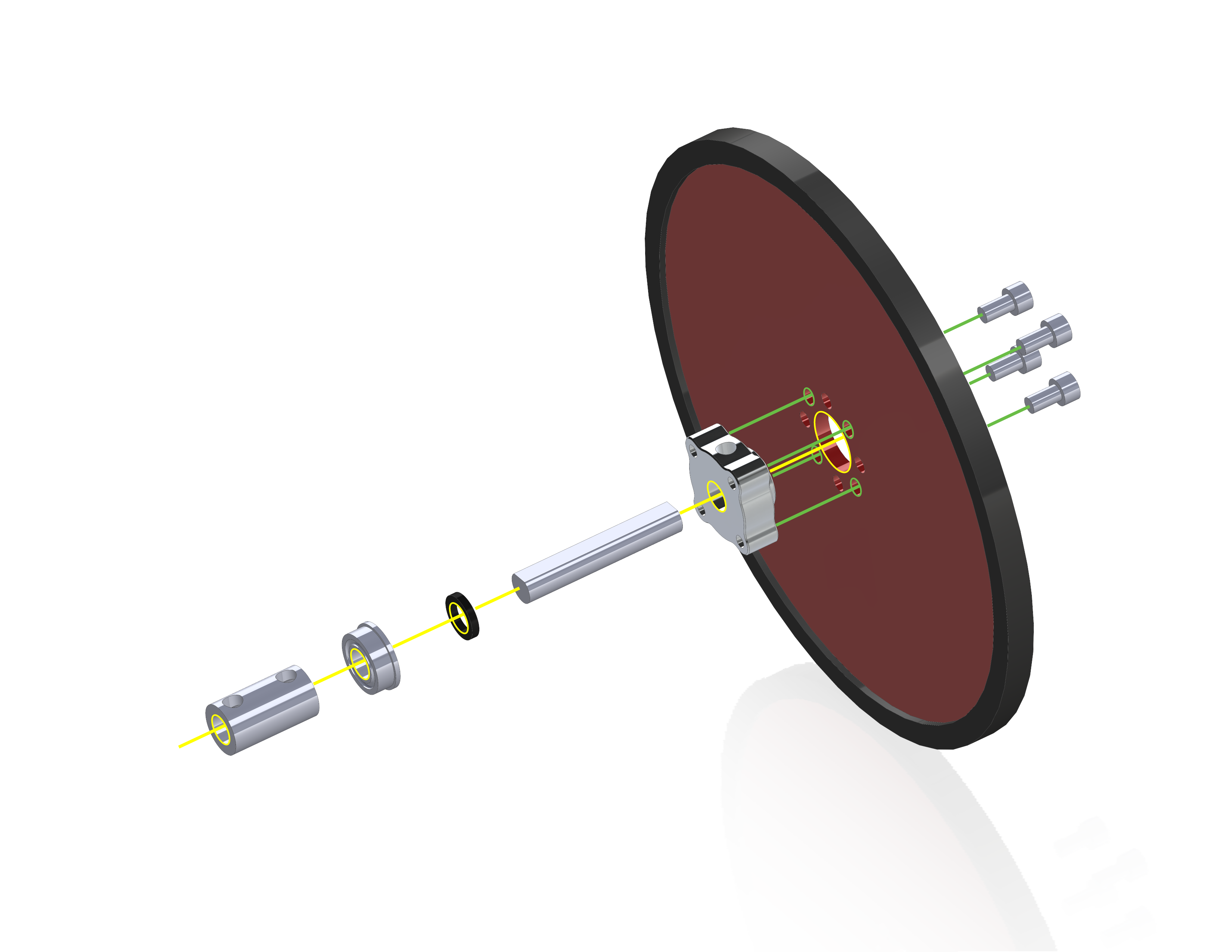
The next assemblies are the left and right axle.
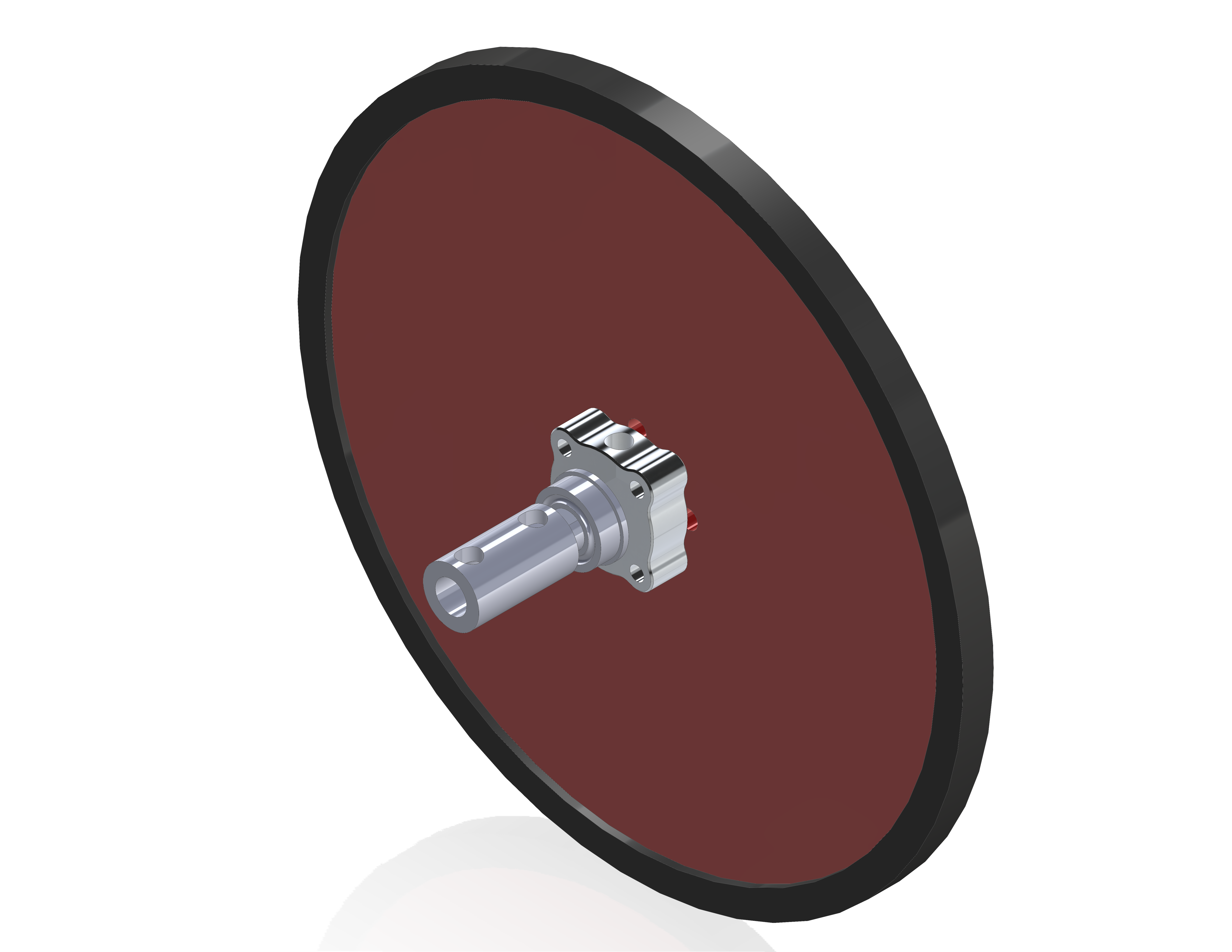
These are identical, so repeat this step for the second side. Attach the large rubber tire to the edge of the precision disc wheel. Then attach the ¼” set-screw hub to the wheel with the raised section of the hub inserted into the center hole of the wheel. Secure the wheel to the hub using four #6-32x ¼” screws. Next insert the D-shaft through the set screw hub, such that the flat side of the shaft is facing the set screw.
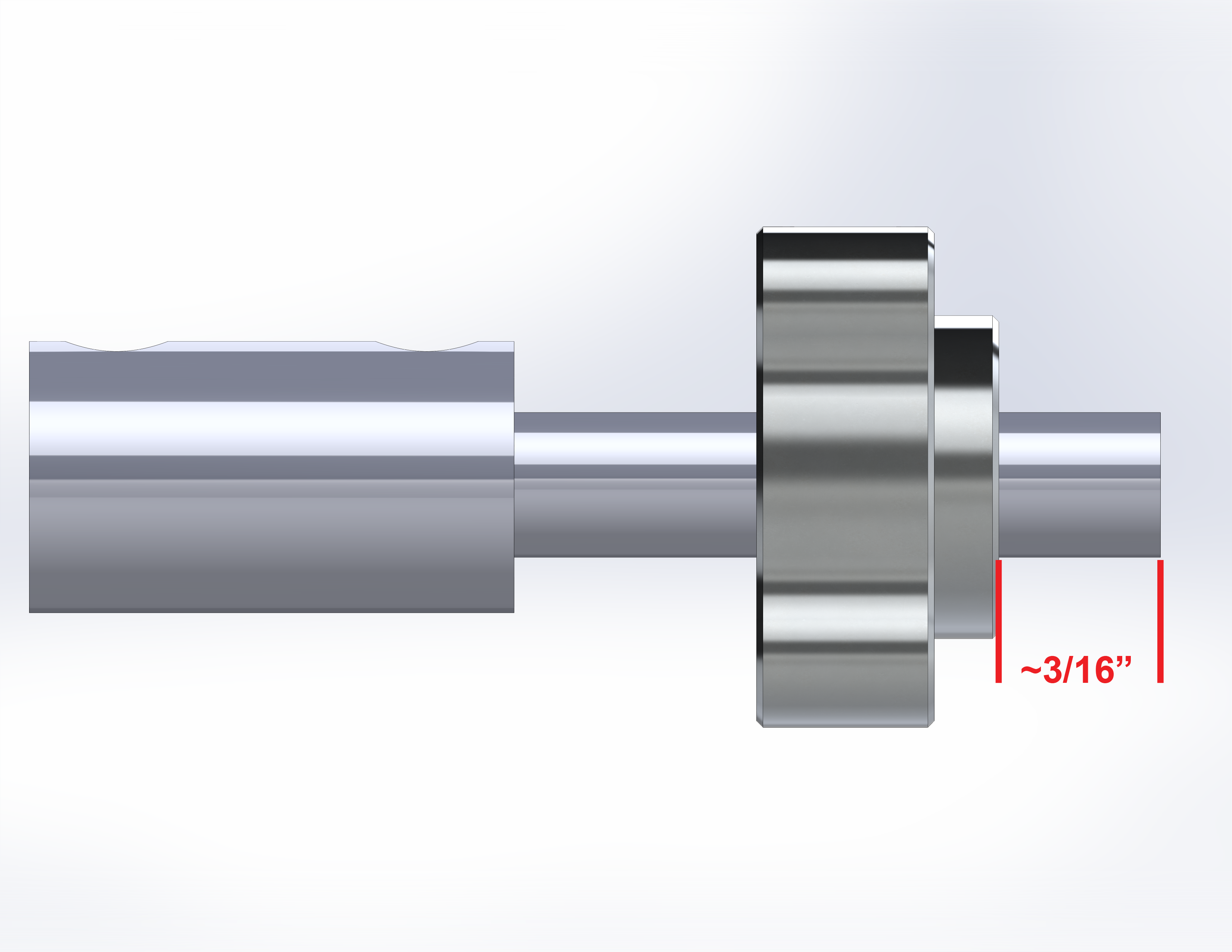
Place the shaft so that about 3/16” is coming out the wheel side of the hub, then tighten the set screw in the hub.
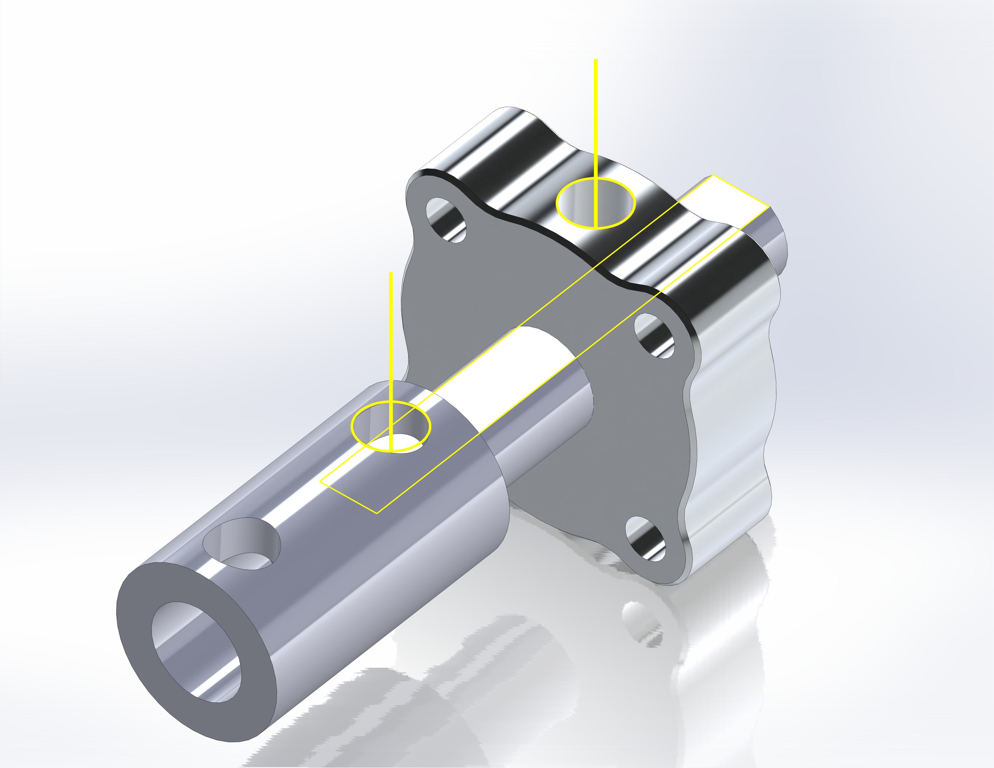
Once the shaft is in place, slide one shaft spacer over the shaft on the hub side, followed by one flanged bearing. Orient the bearing so the flange is on the hub side, next to the spacer. Finally add the shaft coupler by inserting the shaft into the ¼” side (it won’t go into the 6mm side). Again, align the set screw with the flat of the D-shaft and tighten. Repeat for the opposing side.
Motor Mounts
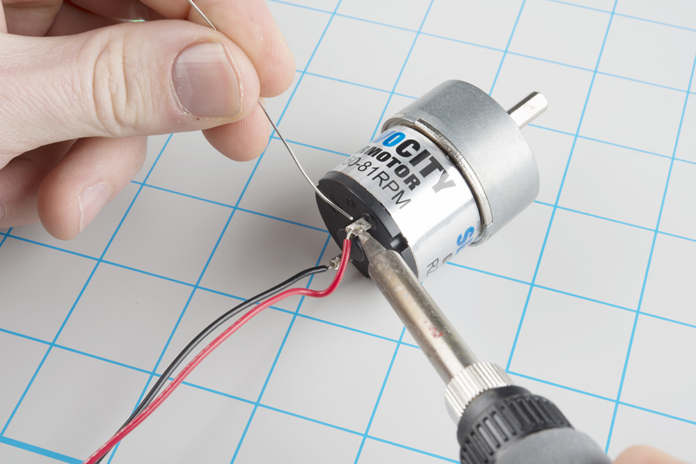
With the axles done, solder wires to the motor leads. Be sure to note the polarity with regard to your wire color.
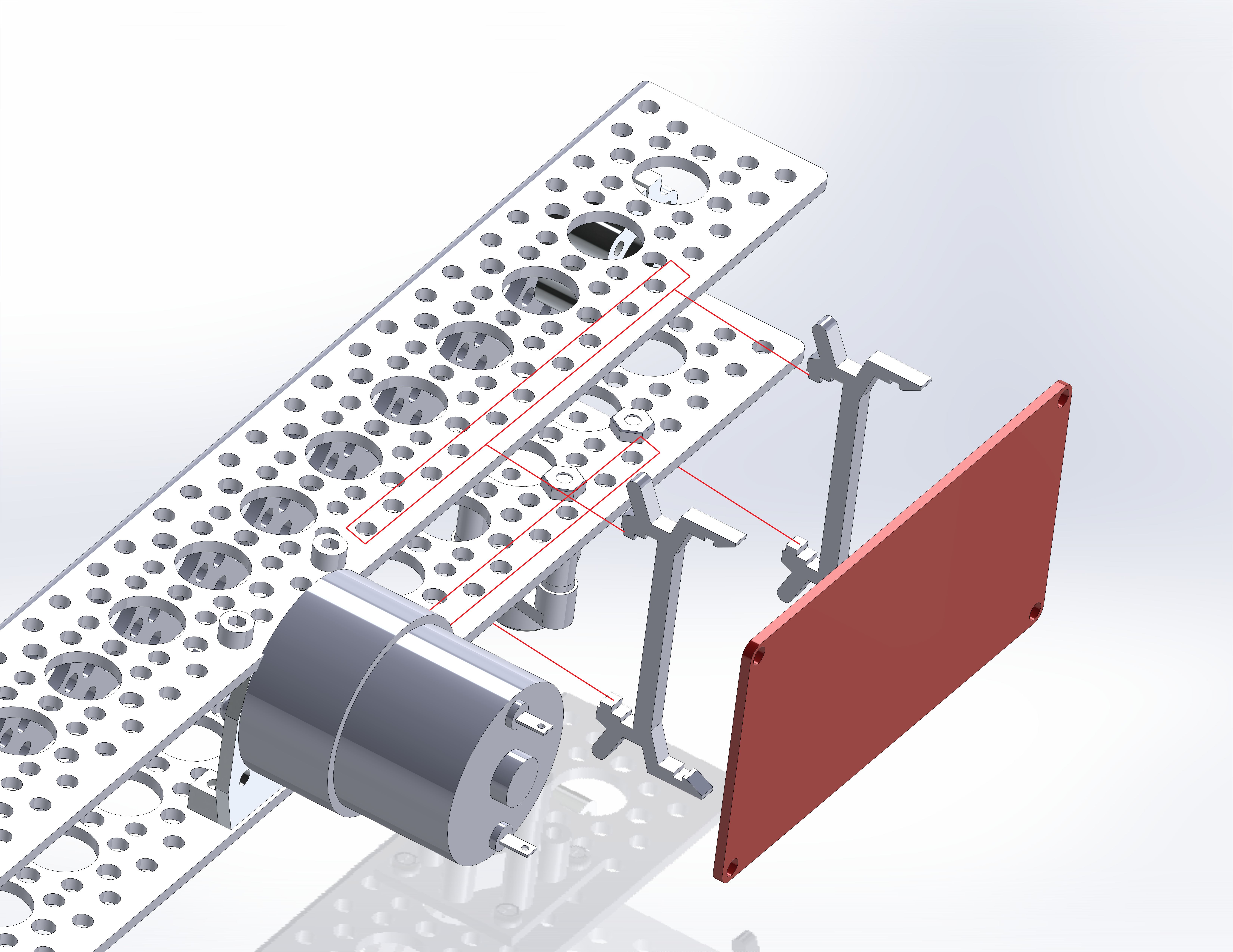
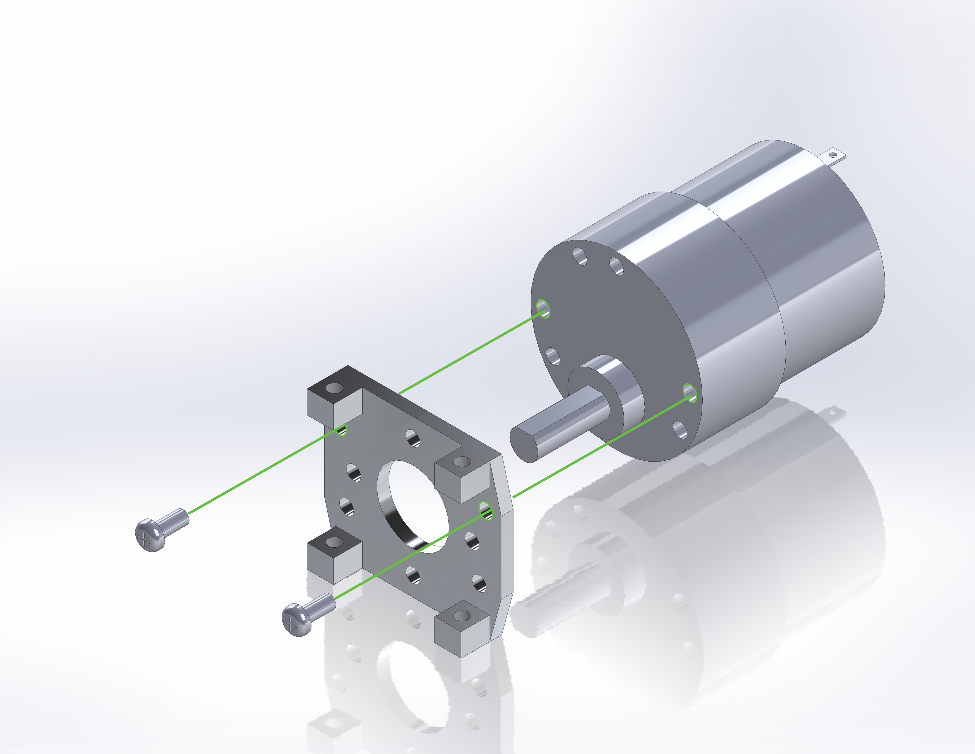
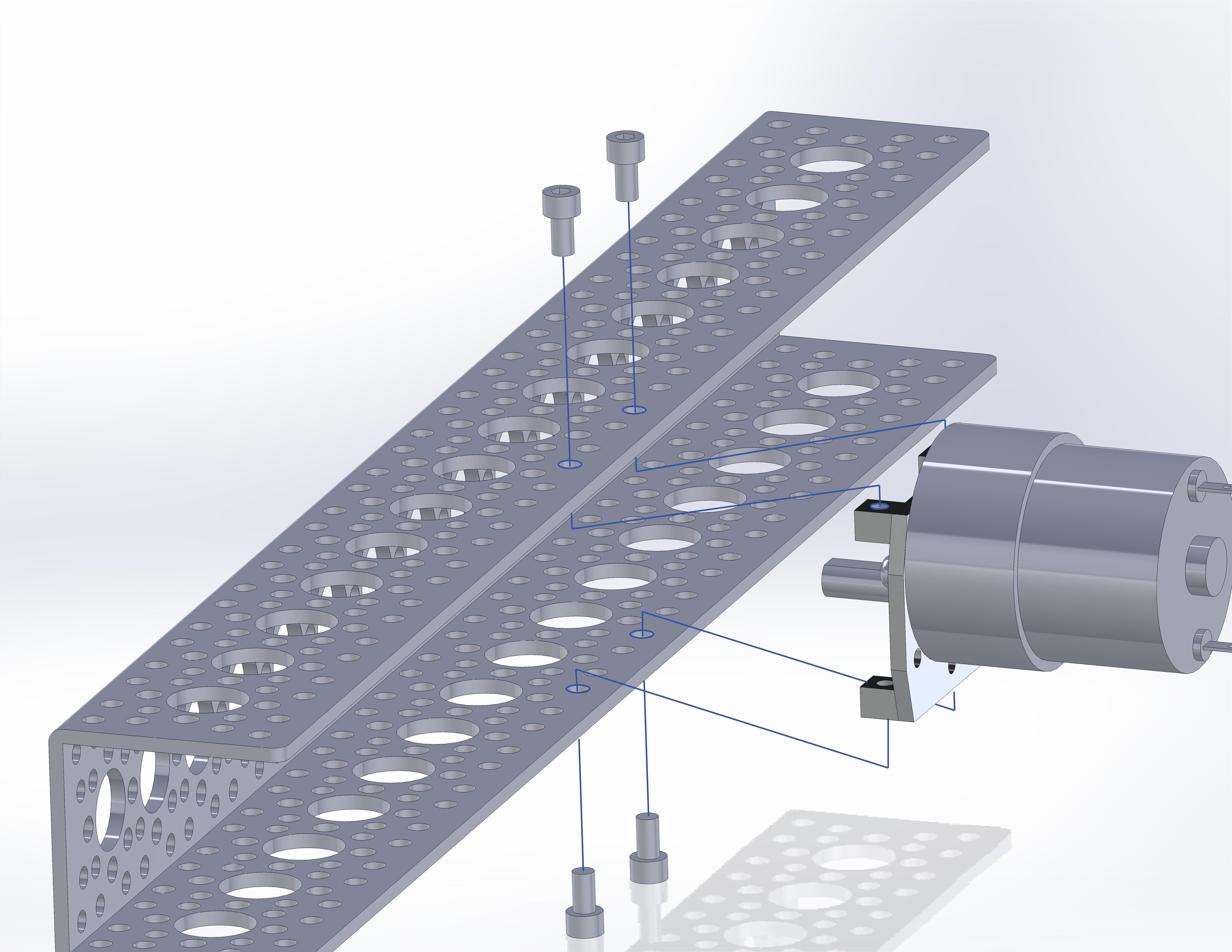
Next, add the motor to the motor mount.
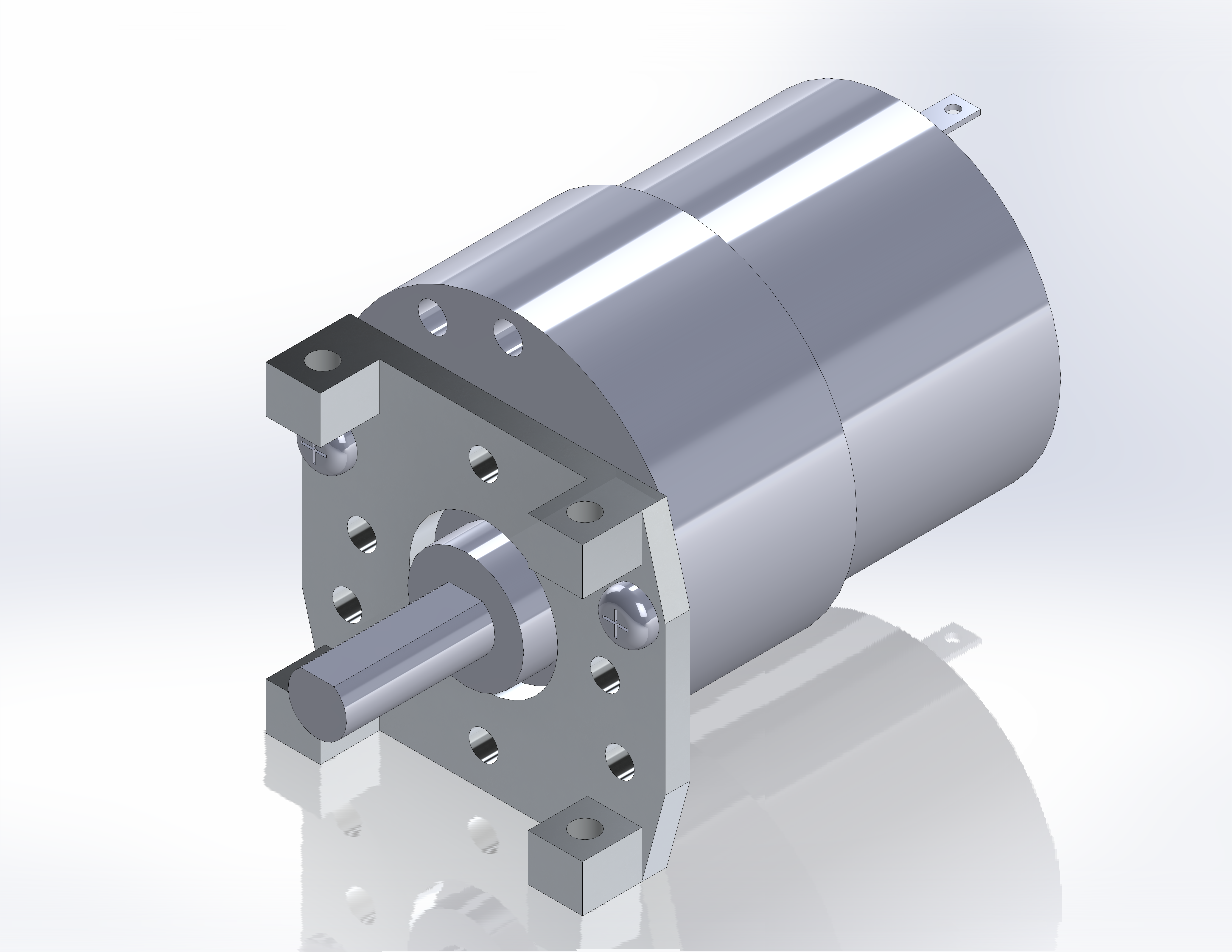
Holding the motor with the output shaft facing you, and oriented at 6:00, locate the holes at 3:00 and 9:00.
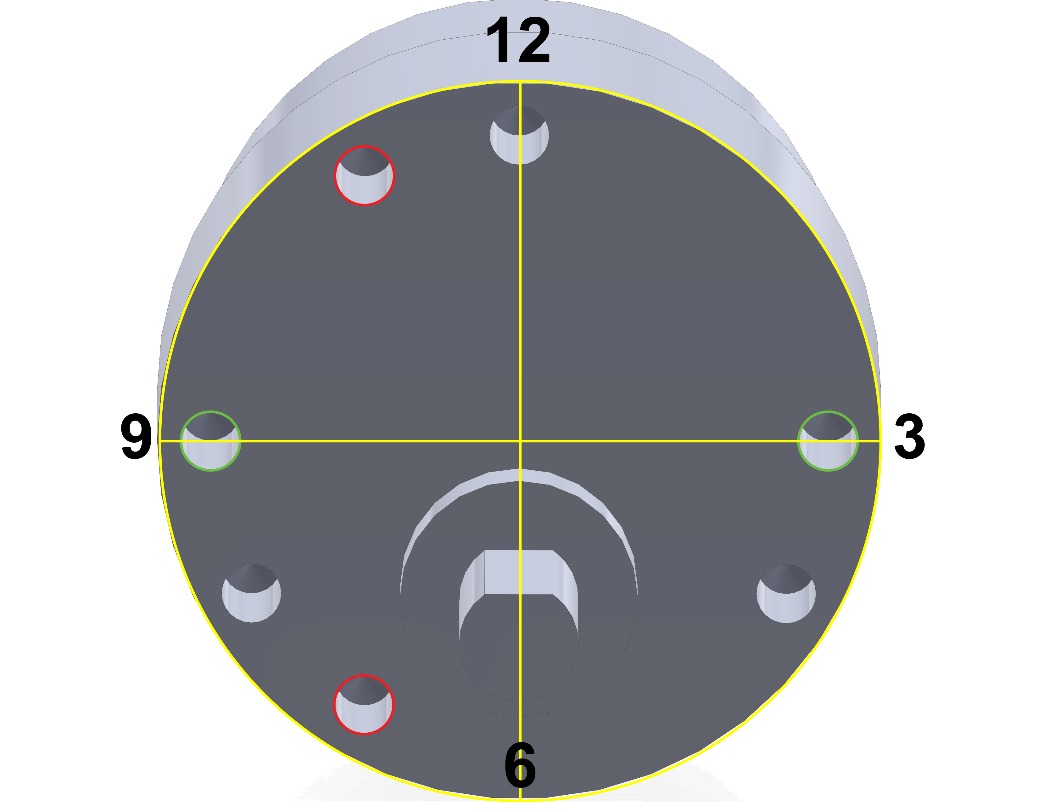
These holes will align with the holes in the motor mount.

Use the holes labelled ‘4’ to align with the motor. Secure with the provided M3 screws. Repeat for the opposing side.
Rail Assembly
With the sub-assemblies complete, we can proceed with building the left and right rails. The channels are the structural backbone of the vehicle so the sub assemblies will be added directly to them.
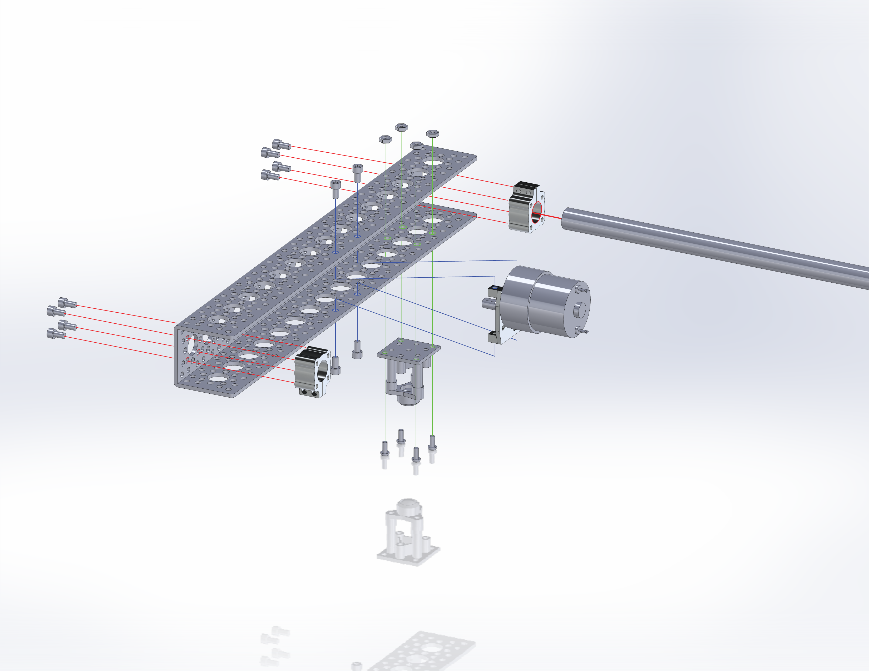
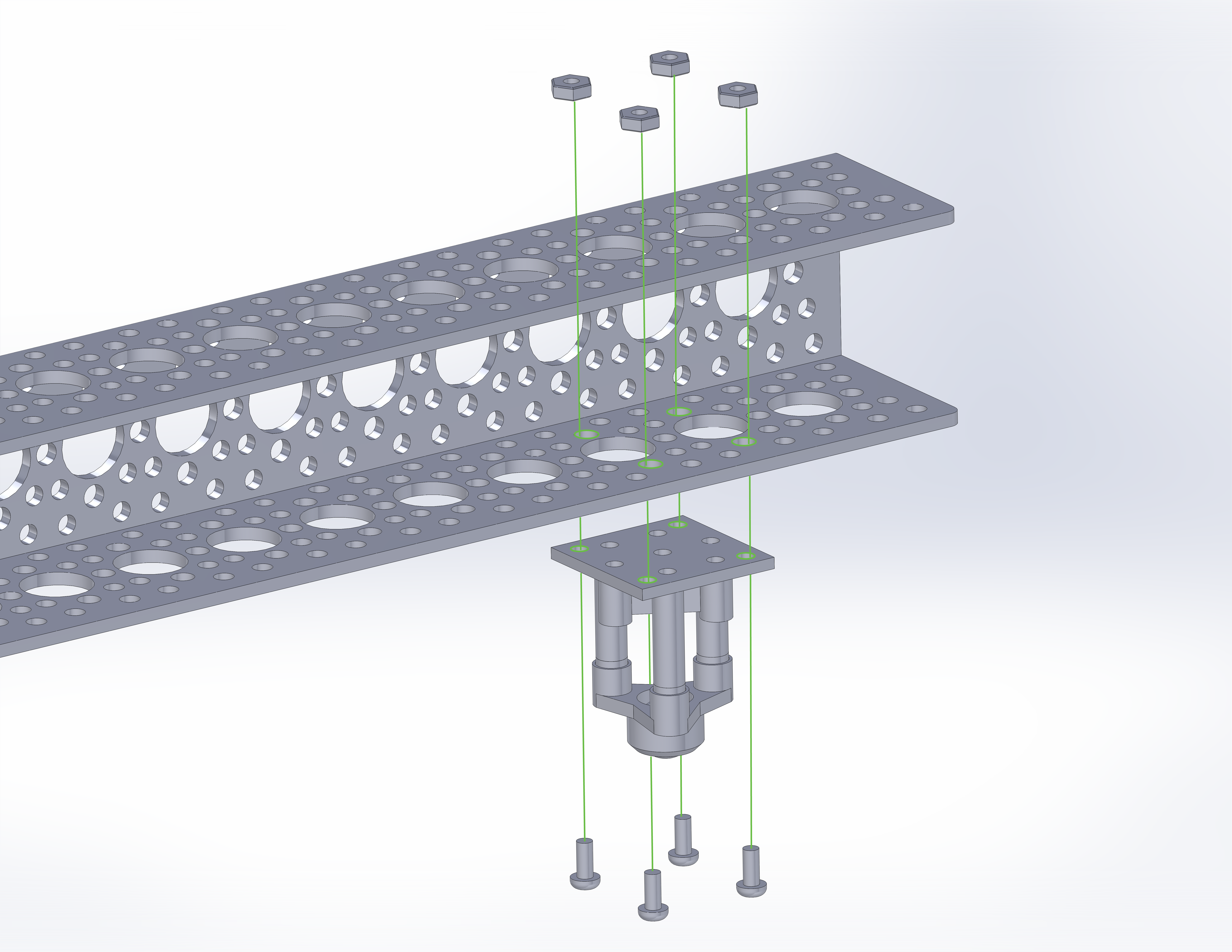
Start by adding a completed caster to the channel in the location shown and secure with four M3x10mm screws and nuts included in the ball caster kit.
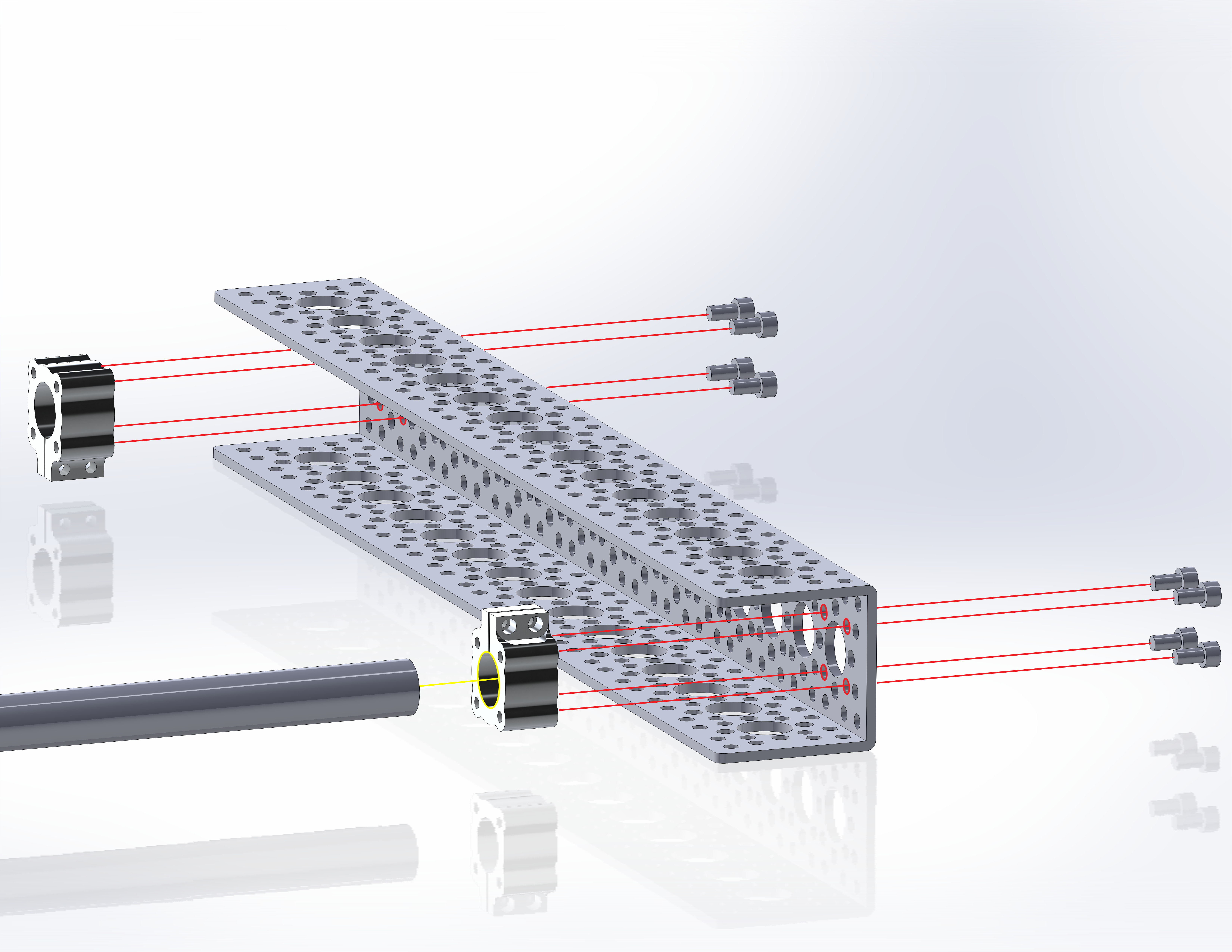
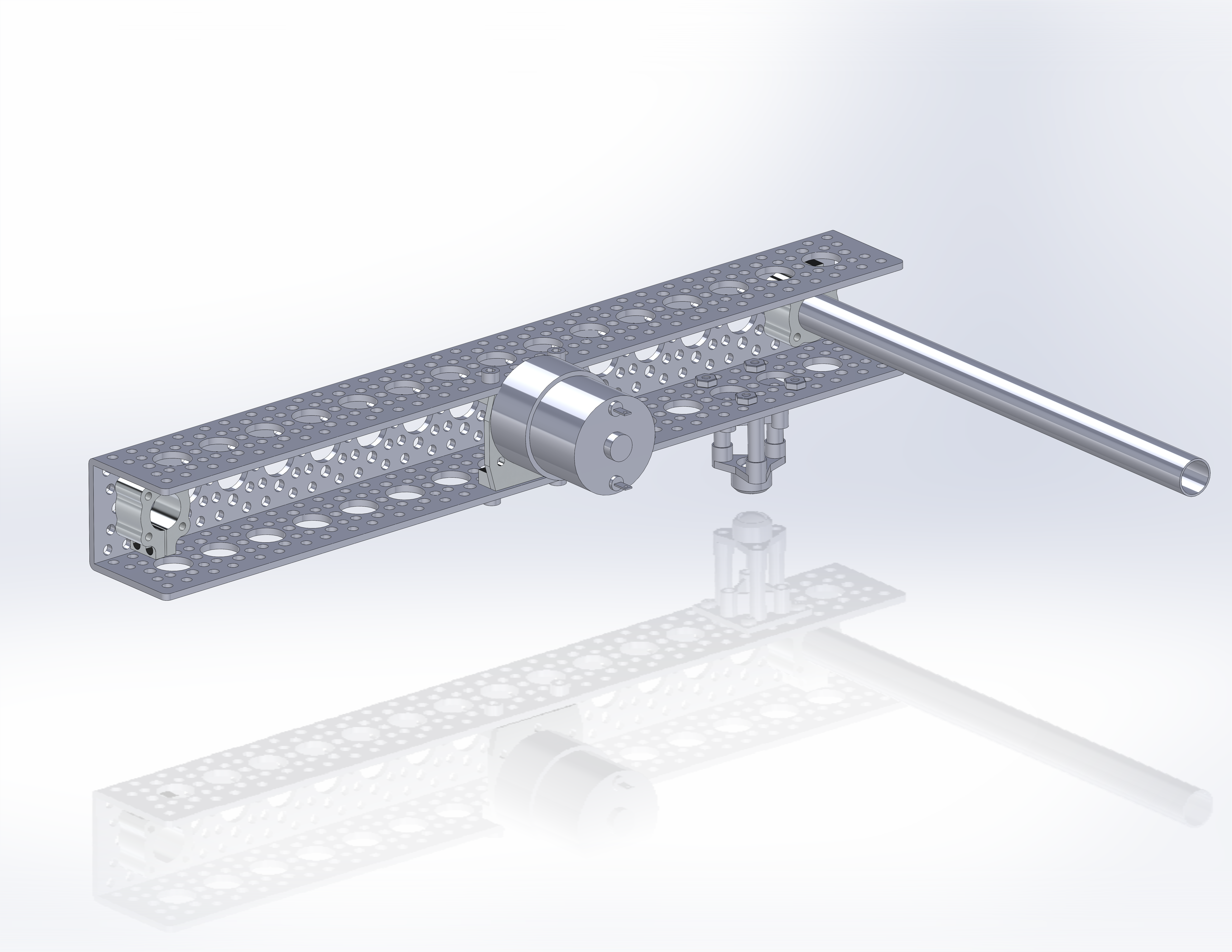
Next add the two #6-32 clamping screws provided with the tube clamps, but do not tighten. Add the clamps in the indicated locations at the ends of the channels. Orient the clamps so that the clamping screw heads are accessible from the ends of the channels. Secure each clamp with four #6-32 screws. Once secure, insert a ½” tube to the clamp near the caster and tighten the clamping screws to lock the rotation of the tube.
Finally, add the motor/mount assembly to the center of the channel. The motor should sit in the “up” position away from the casters. Secure the assembly with four #6-32 screws.
Repeat for the opposing side.
Final Mechanical Assembly
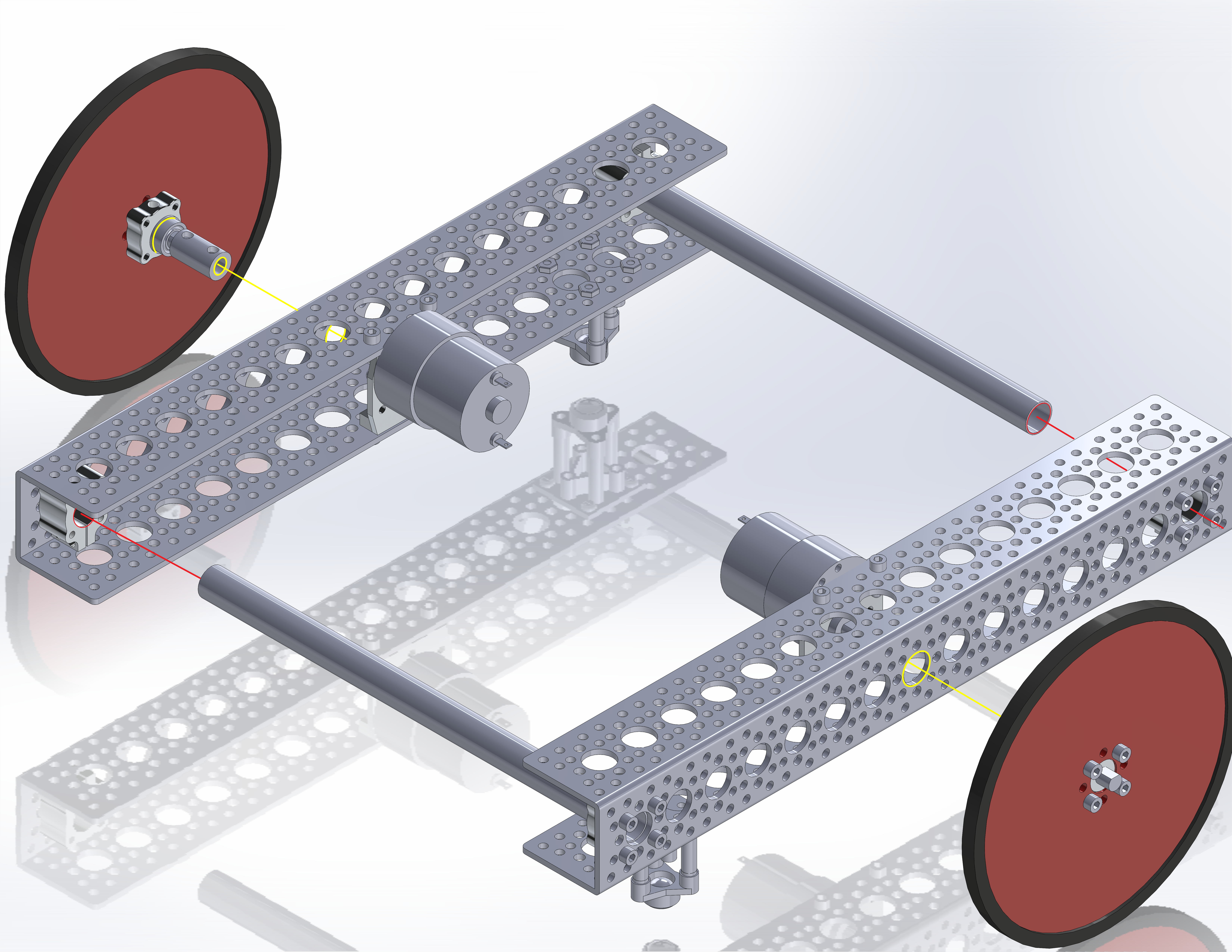
With the rails complete, add them together by inserting the free ends of the tubes into the open tube clamps. Tighten the remaining clamp screws to complete the frame. When finished, it should look like this.

Finally, add the wheel/axle assemblies to the motor shafts. Again, align the set screw on the axle with the flat side of the motor output shaft. Also, be sure that the bearing has fully inserted into the ½” hole in the channel. Tighten the set screw to secure the axle. Repeat for the opposing side. Add a the channel mount clips to one of the rails across the open side of the channel.
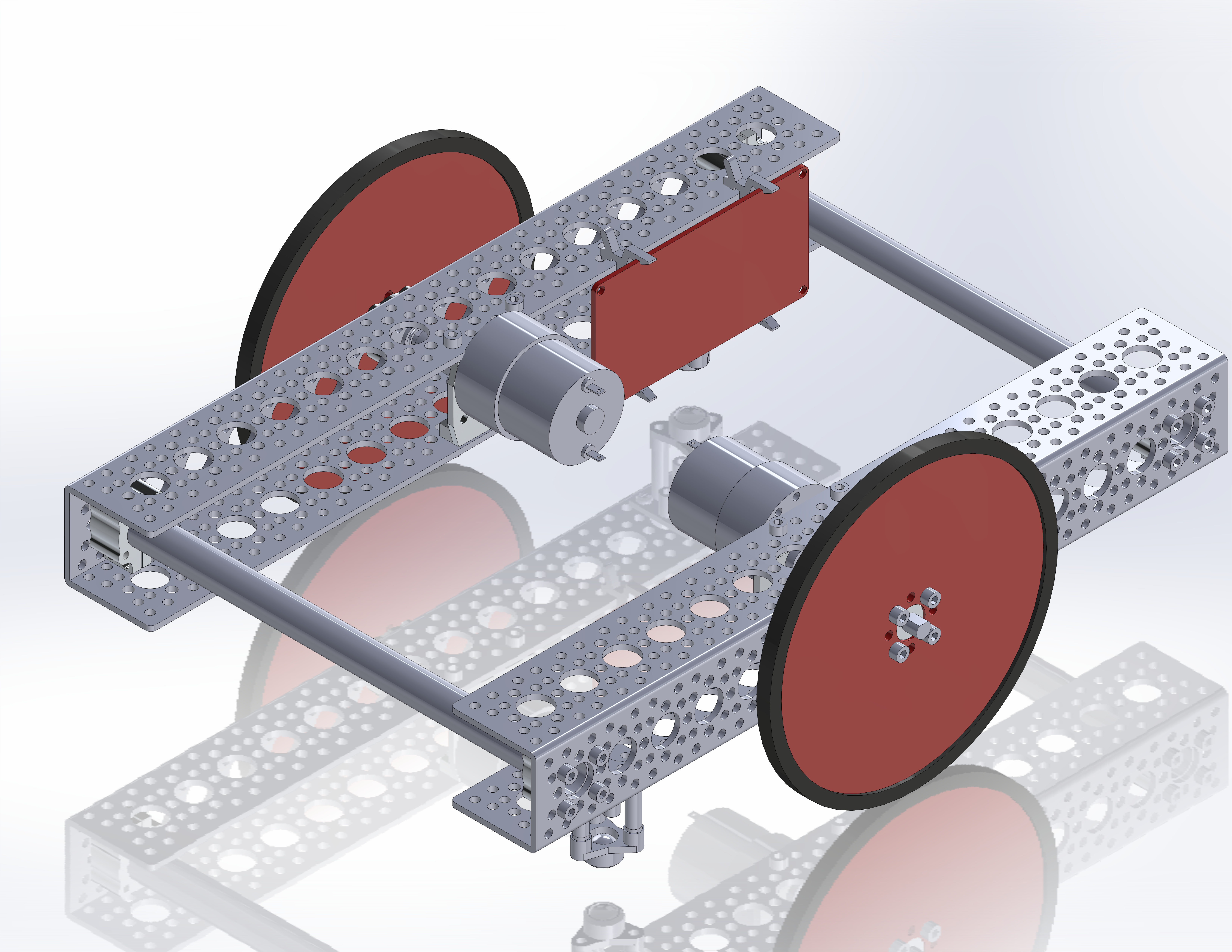
The platform is now complete and ready for control electronics. If you are using an Aruduino Uno or Mega, the board can simply snap into the channel mounts. Tuck a battery behind the mounts and connect the motor lead wires to your motor driver shield.
This example uses the Redbot Mainboard to drive the vehicle via XBee radio control. The Redbot board is secured to the channel using two alternate channel mount clips designed for the RedBoard. The design file is available for download here to laser cut a channel bracket for the RedBot Mainboard.