9DoF Razor IMU M0 Hookup Guide
 jimblom
Hardware Overview
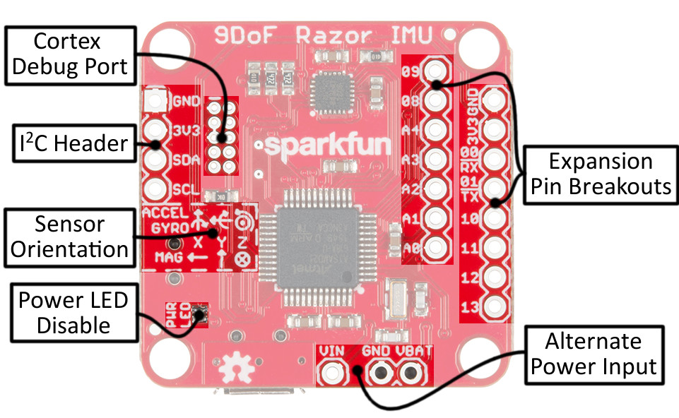
The 9DoF Razor IMU M0 is a double-sided assembly, which means there's a lot going on on both sides of the board. Here's an overview of what we'll call the "top" of the board.
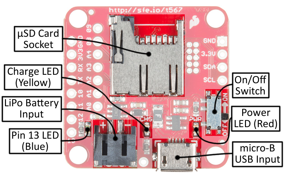
While the bottom of the board includes the various connectors, power control switch, and LEDs.
Open Source Hardware! The 9DoF Razor IMU M0 is an open-source hardware design. Feel free to download the schematic (PDF), Eagle files (PCB design), or browse the design's history in our GitHub repository.
Powering the 9DoF Razor IMU M0
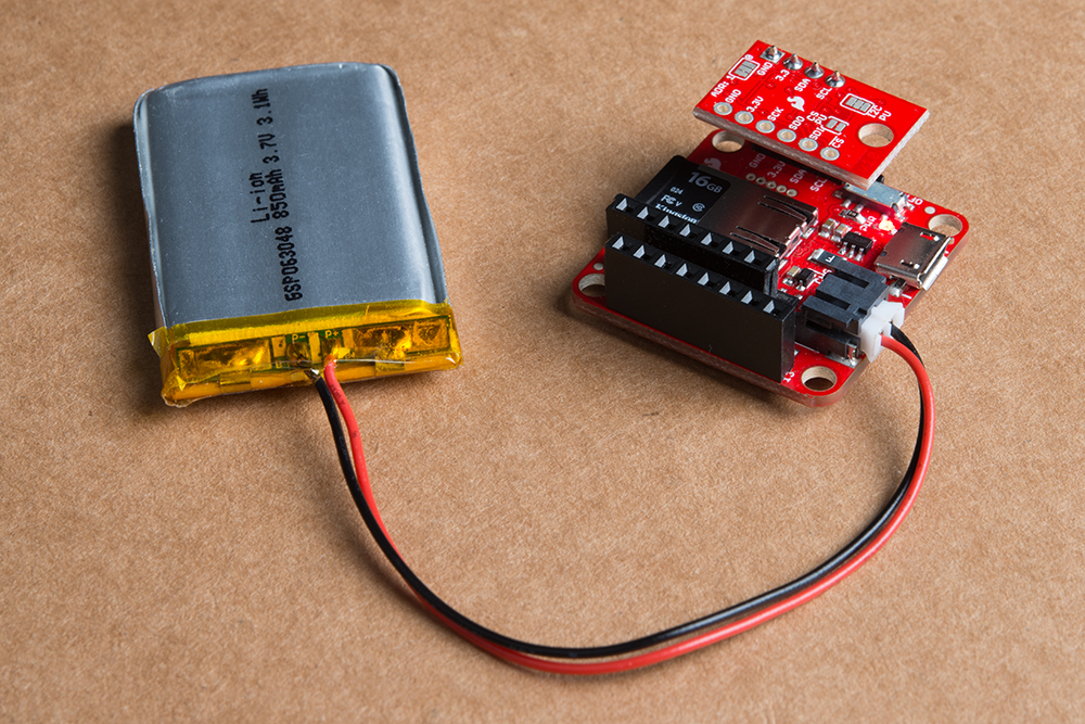
The Razor IMU is designed to work with either a USB power source or a single-cell Lithium-polymer (LiPo) battery. The black, PH-series JST connector should mate with any of the similar LiPo batteries in our catalog -- just make sure they're single cell (nominal voltage 3.7-4.2V).
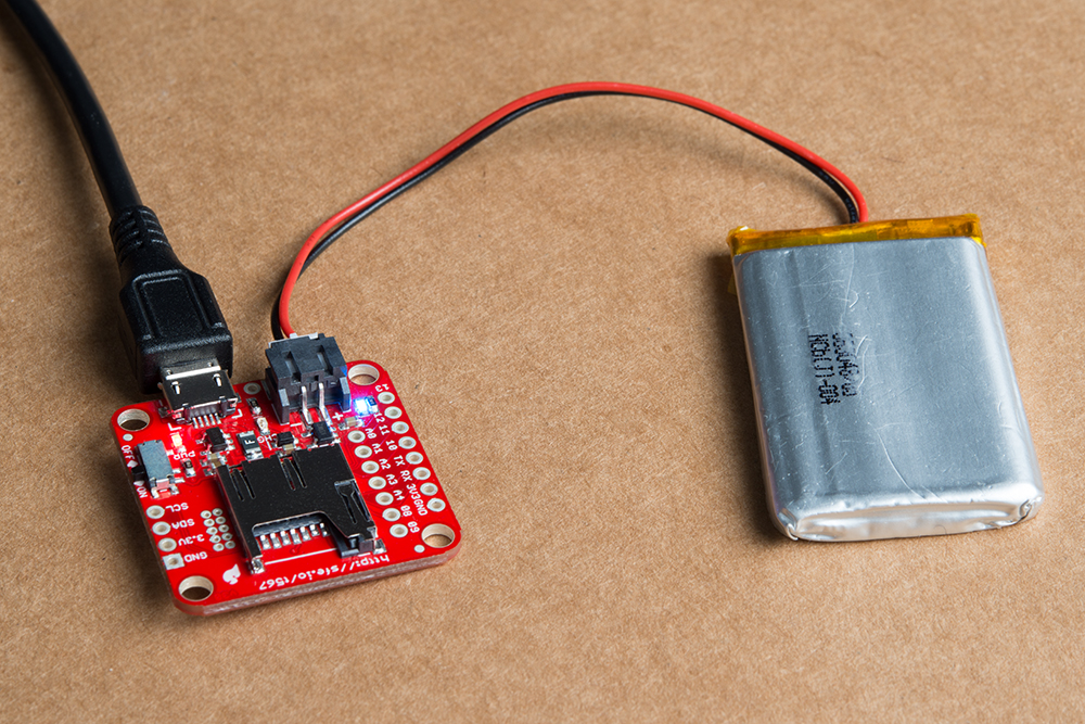
If both USB and LiPo battery are plugged into the board simultaneously, the LiPo will charge at a rate of up to 450mA. Charge status is indicated by the yellow charge LED, which will turn off when the battery is fully charged.
450mA Charge Current The maximum charge current is set by an external resistor and is not (easily) modifiable. Safe practices say not to charge your LiPo battery at greater than 1C, which means LiPo's with a capacity below about 450mAh are not recommended for use with this board.
Power from either the USB or LiPo battery sources are regulated down to 3.3V, which is used to power both the SAMD21 and MPU-9250. The regulator has a capacity for about 600mA, which means you should have plenty of current overhead left over, if you want to power other devices from the 3V3-labeled pins.
The VIN, VBAT, and GND pins can be used to supply the 9DoF Razor IMU's 3.3V regulator, instead of the USB or LiPo JST inputs. Voltage on the VIN pin should not exceed 6V, and the VBAT pin should only be connected to a single-cell LiPo battery.
Finally, the ON/OFF switch, on the bottom side of the board, controls power between both input sources and the rest of the components on the board. While in the "OFF" position, the LiPo battery will still be able to charge, but no other components should be energized.
SAMD21 and Power Supply Pin Breakouts
We've broken out as many of the SAMD21's I/O pins as the 9DoF Razor IMU's small form factor would allow us. That includes pins 10-13, analog-to-digital converter inputs A0-A4, RX, TX, and the I2C pins, SDA and SCL.
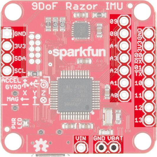
The SDA and SCL pins are on the same I2C bus as the MPU-9250, but that shouldn’t be a problem as long as any additional I2C devices don’t share the IMU’s 7-bit addresses (0x68 and 0x0C).
You can solder headers or wire to these pins, to expand on the board's features. For example, you can plug a BME280 breakout directly into the I2C port, and add altitude and temperature sensing to your IMU.
The SAMD21's single-wire debug (SWD) port is broken out on the top side of the board as well, in case you want to program the chip with a JTAG debugger. The pinout of this port matches the 10-pin Cortex Debug connector standard. A white "notch" indicates pin 1 of this port.
MPU-9250 Accel/Gyro/Mag Orientation
The orientation of the accelerometer, gyroscope, and magnetometer's x-, y-, and z-axes are determined by the placement of the MPU-9250. For easy reference, we've documented these vectors on the top side of the board.
Note that the magnetometer's x and y axes are flipped from those of the accelerometer and gyroscope, and the z-axis is inverted as well.