RETIRED - Pi Wedge Hookup Guide
This Tutorial is Retired!
This tutorial covers concepts or technologies that are no longer current. It's still here for you to read and enjoy, but may not be as useful as our newest tutorials.
View the updated tutorial: RETIRED - Pi Wedge B+ Hookup Guide
 Byron J.
Introduction
The Raspberry Pi seems to be popping up all over the place. It's a small, inexpensive board with a lot of number-crunching capability. It can run a standard Linux distribution, and supports a lot of common Linux applications, including programming languages like C, C++, and Python. This makes it very useful for tasks that need more horsepower than a small 8-bit microcontroller provides, or that can take advantage of the feature-rich environment that Linux offers.
After building several projects using the Raspberry Pi, we found some growing pains in building prototypes that incorporated external hardware. The Pi Wedge is a small board that connects to the GPIO connector, and breaks the pins out into rows that work with solderless breadboards.
This guide will show you how to assemble the Pi Wedge, and start using it with your Raspberry Pi.
Required Materials
- The Pi Wedge kit
- A Raspberry Pi single board computer. The Wedge works with both Model A and Model B
- A Solderless Breadboard
- An FTDI Basic
- Your favorite I2C, SPI or GPIO-based peripherals
- A soldering iron and leaded or lead-free solder
Suggested Reading
Suggested Viewing
Background
In the process of developing projects like the Twitter Monitor and Great American Tweet Race around the Raspberry Pi, we found that we were experiencing some growing pains when trying to expand the Pi into a prototype that involved external hardware.

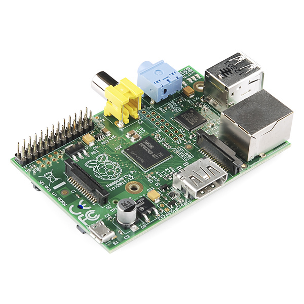
The Raspberry Pi has a 26-pin connector that provides access to several communication interfaces, plus GPIO and power. But the connector doesn't have detailed labeling, and the native pin arrangement is somewhat scattershot. Pins used for similar functions aren't always grouped together, and power and ground pins are interspersed with no obvious pattern.
The pins also don't translate to a solderless breadboard very easily. Our first projects used a bunch of F-M jumper wires that we just plugged into the header. They involved a lot of "ratsnest jiggling" when things stopped working.
Bootstrapping
In addition to the physical issues of using the I/O connector, getting started with a brand new Raspberry Pi always seems to involve a chicken-and-egg situation. We just want to SSH into it, so we can use the command line. But in order to SSH to it, we need to know it's IP address...and of course, the IP address is most easily learned by running ifconfig on the command line.
The Solution
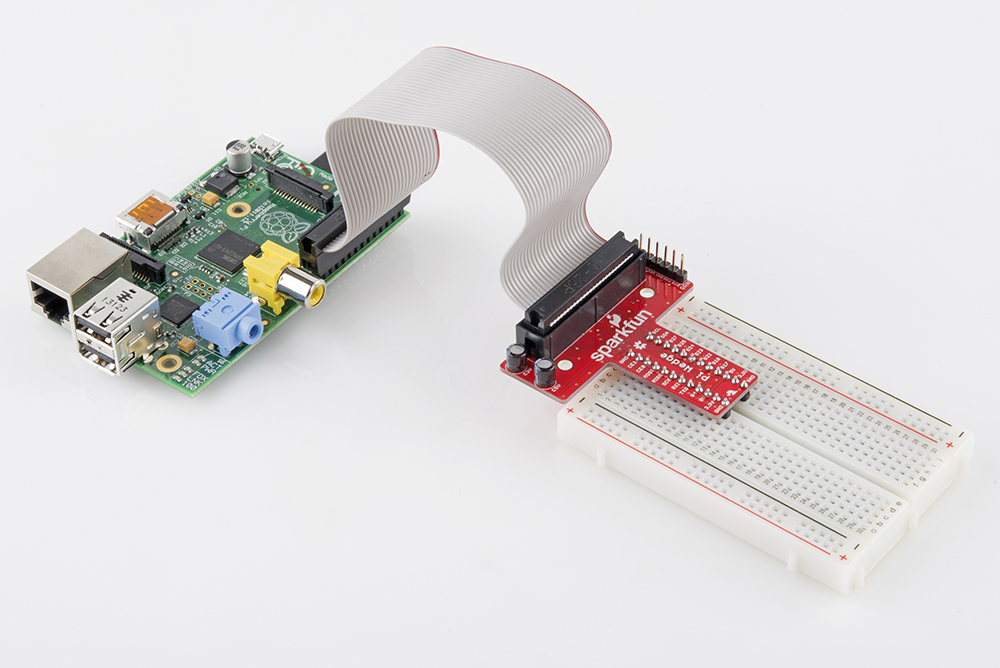
The Pi Wedge connects to the 26-pin GPIO connector, and breaks out the pins in a breadboard-friendly arrangement and spacing. It even adds a pair of decoupling capacitors on the power supply lines, and it makes the initial bringup process easier - you can plug an FTDI Basic module into the serial port.
Assembly
The Pi Wedge comes to you as loose parts, which you need to assemble before you can use it. The following steps will guide you through the assembly process.
Kit Contents
Let's start by reviewing the contents of the Pi wedge kit.
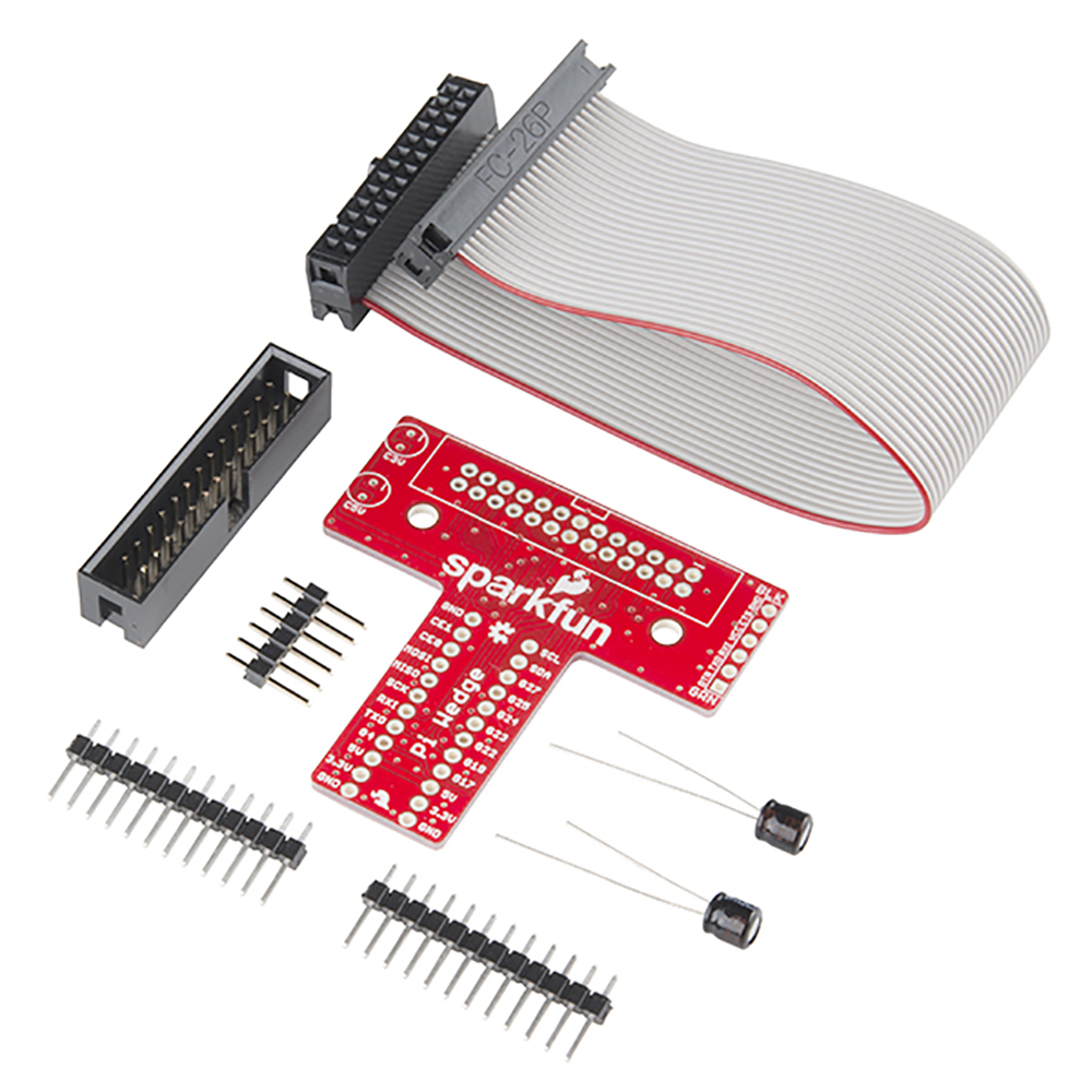
You should have the following parts.
- Ribbon cable
- Pi Wedge PCB
- 26-pin shrouded header
- 6-pin straight header
- 2x 12-pin straight headers
- 2x 10 uF 25V electrolytic capacitors
Instructions
Assembly of the Pi Wedge should be mostly obvious and straightforward. One thing to notice is that components are soldered to both sides of the board. The headers that interface with the breadboard are on the bottom of the board, soldered from the top. The other components go on the top, and are soldered from the bottom.
Pin Alignment
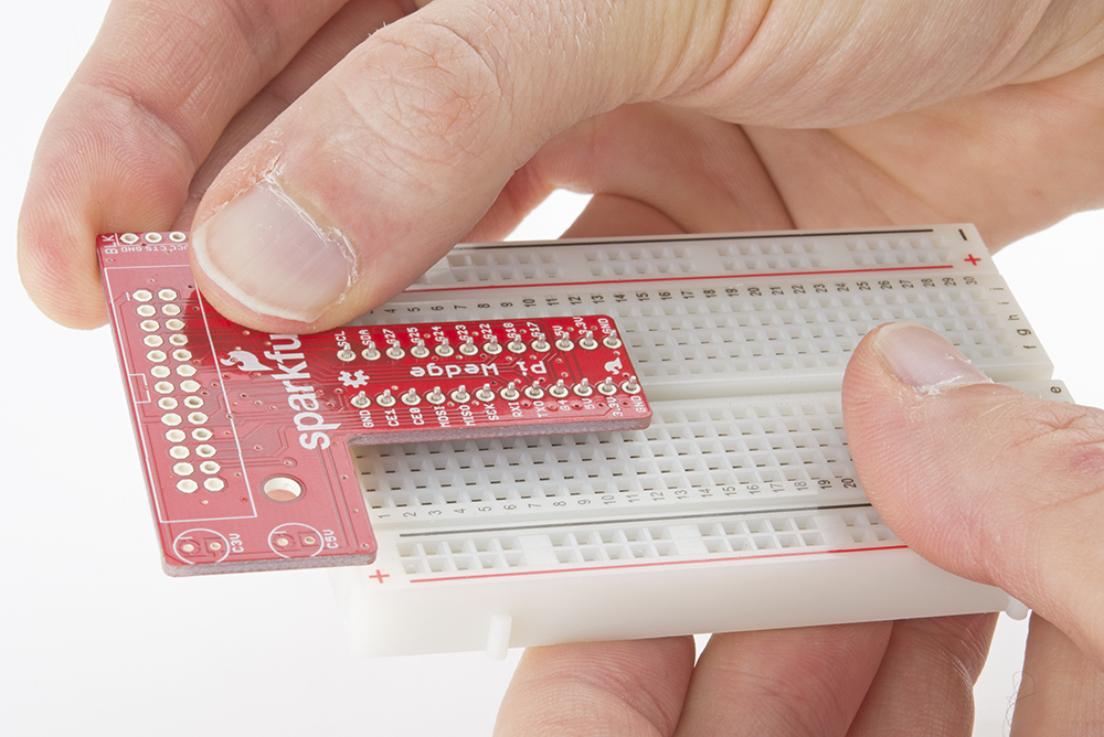
To keep the breadboard pins properly spaced and aligned while you solder, you can use your breadboard as an assembly jig. Simply insert the 12-pin headers in the breadboard...
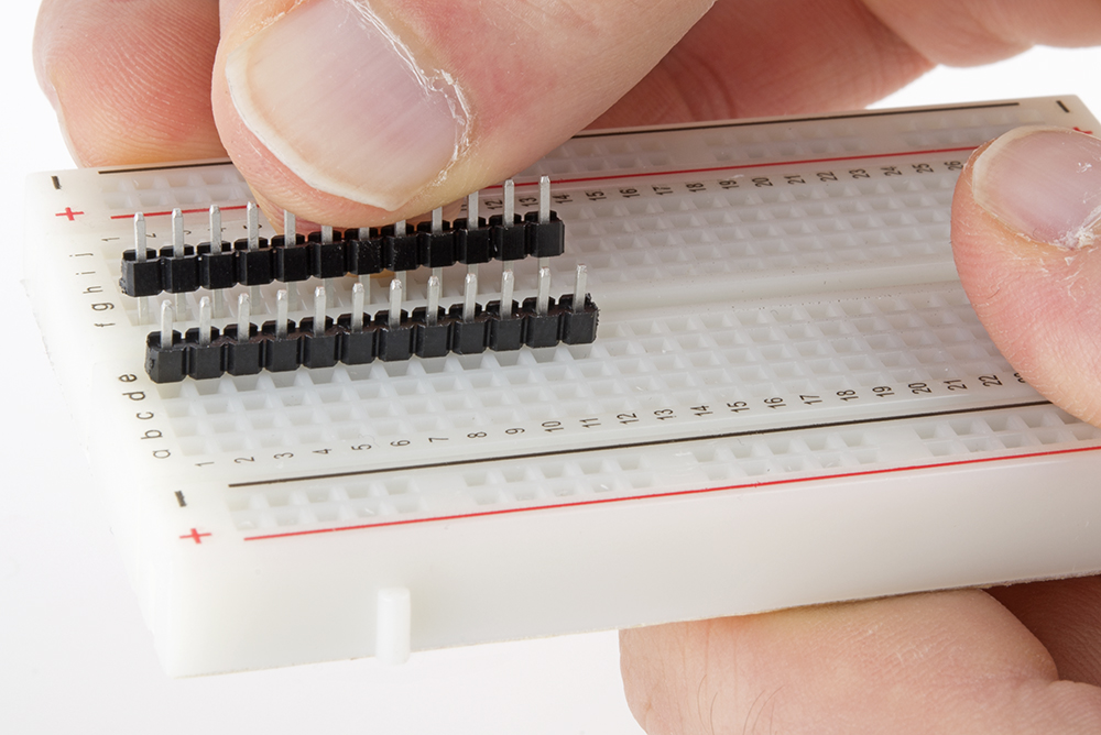
...then place the PCB over them, and solder it in place. Notice that the PCB is placed over the pins so that the signal labels are facing up.
Be careful not to overheat and melt the breadboard while soldering the pins on. Zig-zagging between the rows will help distribute the heat. Also, somewhat counter-intuitively, using a hotter setting on your soldering iron will allow you to work more quickly, minimizing the risk of melting the breadboard.
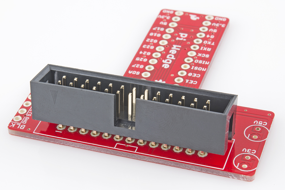
Shrouded Header
The shrouded header has a notch that keeps the ribbon cable properly oriented. The notch should be lined up with the corresponding rectangle in the PCB silkscreen.
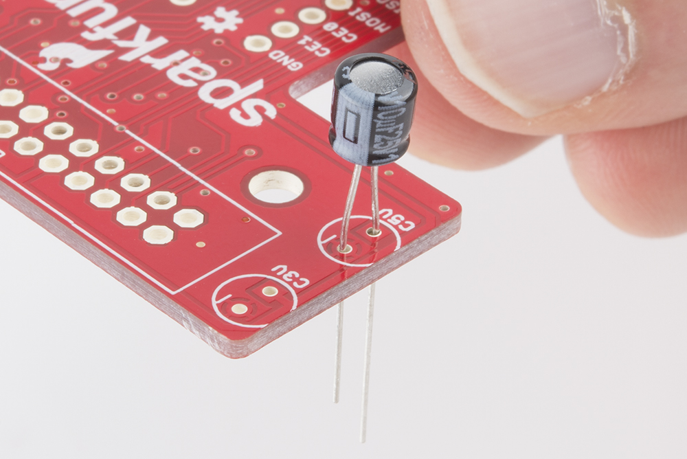
Capacitors
The electrolytic capacitors are polarized. The body has a band of "-" signs near the negative lead, which should be inserted into the PCB hole marked with the - sign. The negative lead is also shorter than the positive lead.
Serial Adapter Connector
The 6-pin header is soldered onto the PCB across from the capacitors.
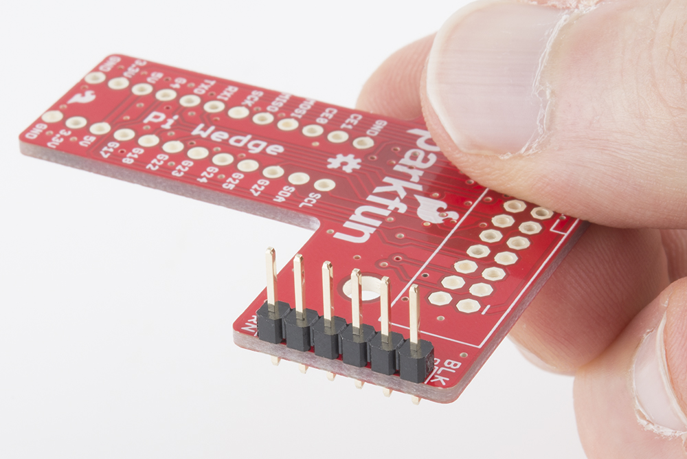
If you want a lower profile assembly, you can substitute a right-angle header for the straight pins in the kit.
Connection
With the wedge soldered together, you're ready to attach it to your Pi, and test it out.
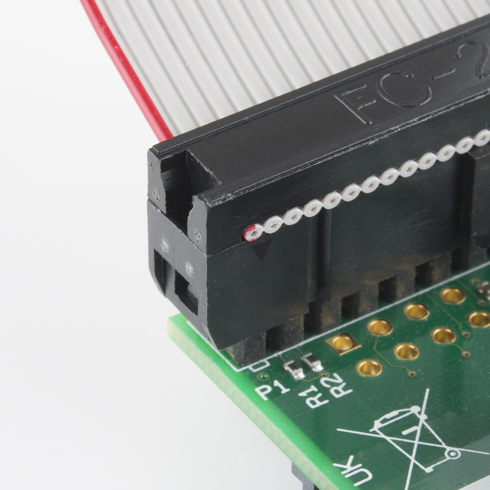
The ribbon cable is polarized. On the Pi Wedge, the tooth on the cable will interface with the notch in the shrouded header.
The header on the Pi itself doesn't have anything to help guarantee the alignment. You'll need to take care that it gets connected properly. Pin 1 on the Pi is marked with a small rectangle in the silkscreen layer. The ribbon cable connector is embossed with (a barely visible) small triangle that marks pin 1, and the first pin is also coded on the wire, such as the red stripe in the photo below (though it may also be another color, such as black or dark blue).
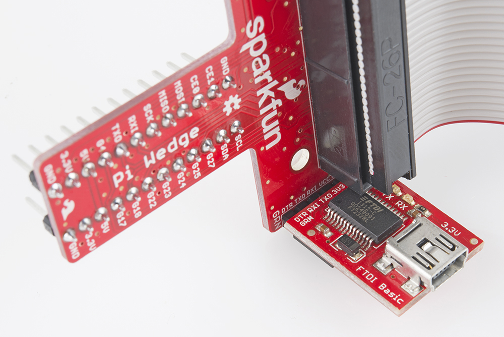
The FTDI connector also needs to be aligned correctly. Be sure to match up the "grn" and "blk" markings on both boards.
On the next page, we'll explore how the signals from the Pi are mapped to the Wedge.
Pin Mapping
Revisions
The pins on the Raspberry Pi changed between Revision 1 and Revision 2 - a few signals were reassigned. The physical connection is the same, but you'll need to know which version of Pi you're using to address the pins correctly.
The Wedge is labeled with the Revision 2 labels. You'll need to translate a few things if you're using a Revision 1 Pi. In short - to use the Wedge with a Revision 1 Raspberry Pi, do the following.
- Be sure to use
/dev/I2C0instead of/dev/I2C1. - Use GPIO 21 instead of GPIO 27.
Alternately, use a software library such as Wiring Pi that can identify the revision and abstract the pin numbers. We'll cover WiringPi in more detail in the software section.
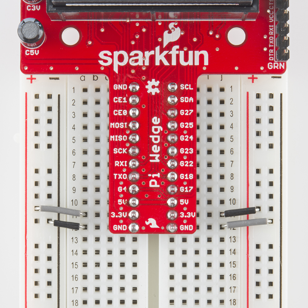
Signal Location
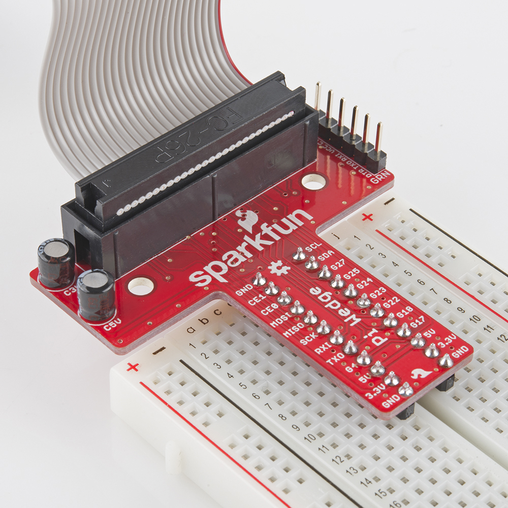
The Pi Wedge reorganizes the I/O pins on the Pi, putting similar functions on adjacent pins. The SPI, I2C and UART signals are all grouped near each other.
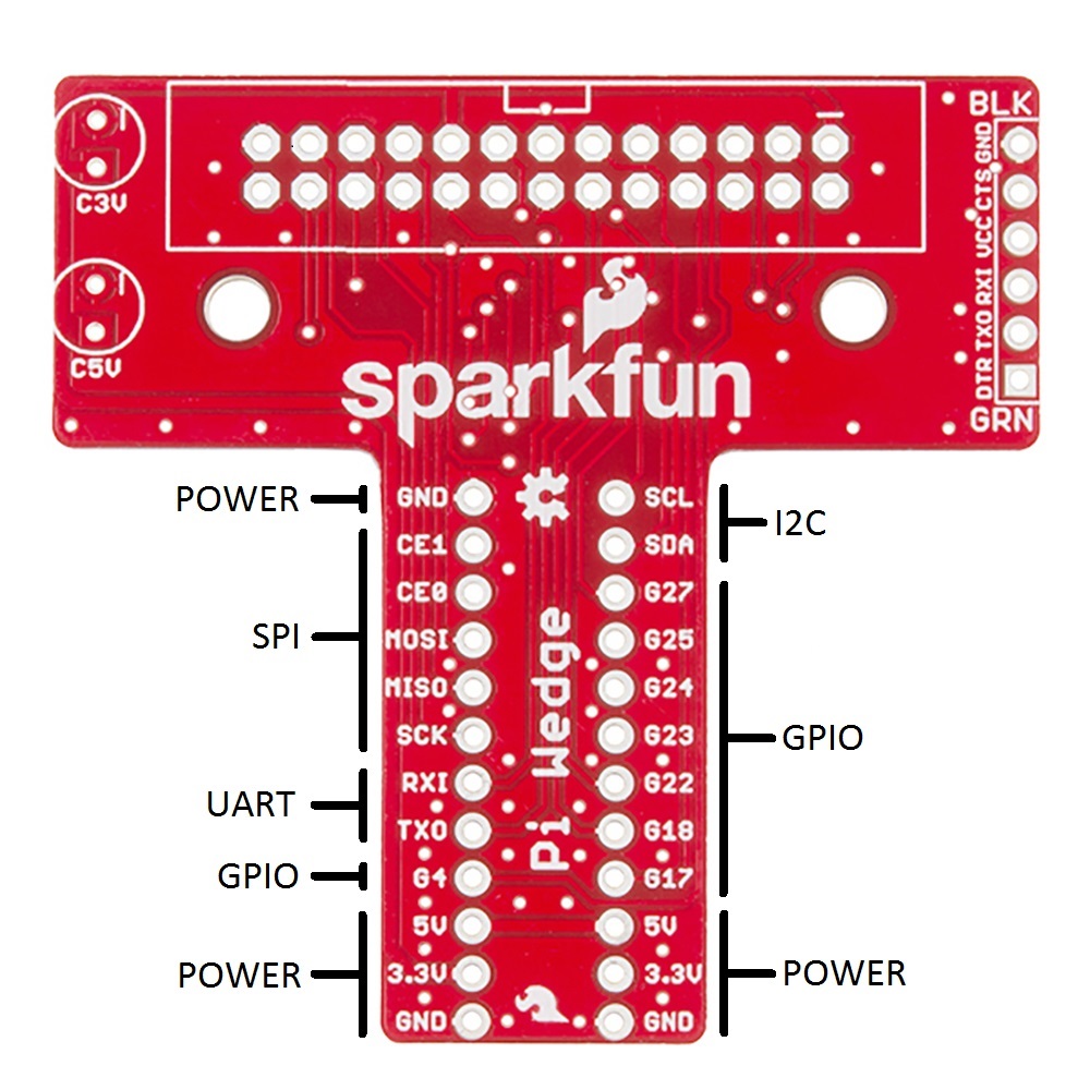
The pins are labeled, though the labels are short to fit the space available on the PCB. The UART, SPI and I2C pins are marked with their communication bus functions, but they can also available as GPIO pins when initialized in that mode.
The following table denotes the assignment of signals on the Pi Wedge, including the peripheral and alternate GPIO assignments where appropriate.
| Function | GPIO# | Function | GPIO# | |
| Ground | R0: SCL0 R1: SCL1 | R0: GPIO1 R1: GPIO3 | ||
| SPI0 Chip Enable 1 | GPIO 7 | R0: SDA0 R1: SDA1 | R0: GPIO0 R1: GPIO2 | |
| SPI0 Chip Enable 0 | GPIO 8 | R1: GPIO 21 R2: GPIO 27 | ||
| SPI0 MOSI | GPIO 10 | GPIO 25 | ||
| SPI0 MISO | GPIO 9 | GPIO 24 | ||
| SPI0 Shift Clock | GPIO 11 | GPIO 23 | ||
| UART Rx | GPIO 15 | GPIO 22 | ||
| UART Tx | GPIO 14 | GPIO 18 | ||
| GPIO 4 | GPIO 17 | |||
| 5V | 5V | |||
| 3.3V | 3.3V | |||
| Ground | Ground |
Power And Logic Levels
Power
Understanding the Pi's power supply is critical to using it successfully.
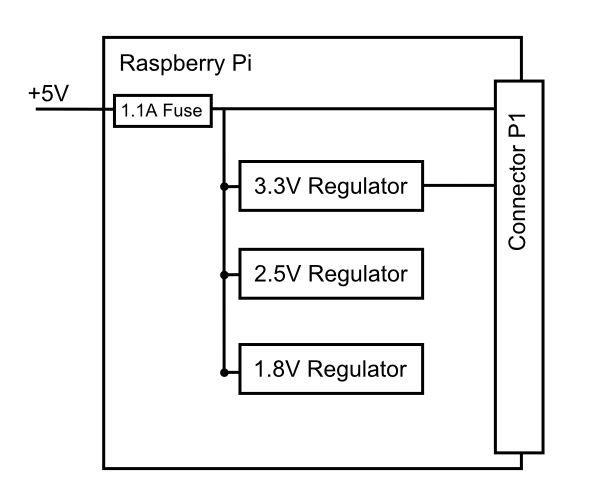
Consulting the Raspberry Pi schematic, we see that 5V comes into the the board via connector S1 - it's a micro USB connector, but only the power and ground pins are connected. The 5V coming from this connector passes through a fuse, then continues around the board without any further regulation. The 5V connections on the Pi Wedge come straight from this line.
On the Pi, the 5V goes to a set of daisychained regulators that further reduce it to 3.3v, 2.5V and 1.8V. The regulated 3.3V is present on the I/O connector.
To power small circuits on your breadboard, you can run jumpers from the 5V or 3.3V and Ground pins on the wedge to the power rails on the breadboard.
Be aware that there's not a lot of juice available from the Pi. The Pi foundation states that the max draw from the 3.3V pins is 50 mA. In our experience, that's not a lot. When we built a display with a string of alphanumeric LED modules, we reached the point that turning on too many LED segments caused the CPU to reboot.
Similarly, the current available on the 5V pins is constrained by the fuse and limits of the attached USB port.
If you want to drive a lot of circuitry from a Pi, you'll need to use a more robust power distribution scheme. One example would be to use an external power supply, connected directly to each portion of the system. For peripherals that use 5V logic, it would also involve logic level translation.
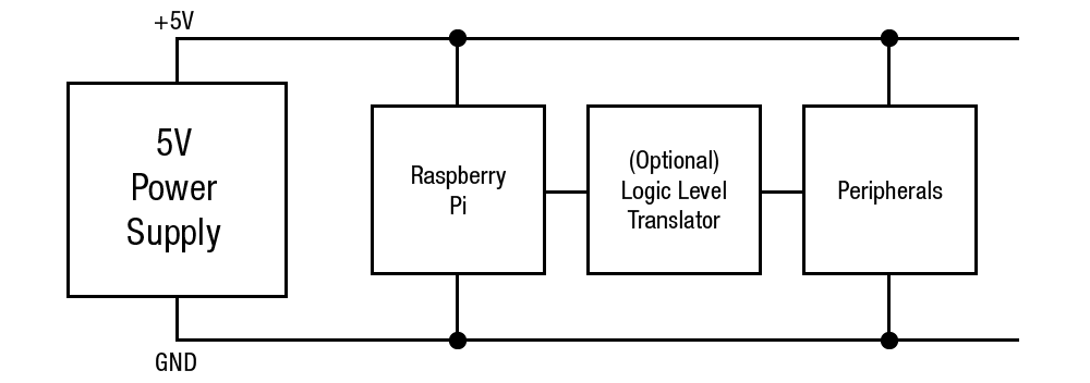
Logic Levels
The Pi uses 3.3V logic levels, which are not 5V tolerant. Many peripheral devices are capable of running at 3.3V, but in the case that you need to interface with 5V devices, use a level shifter, such as the TXB0104 breakout.
Communications
Finally, the signals on the 6-pin FTDI header are also limited to 3.3v logic levels. Be sure to use it with a 3.3V FTDI module, and not a 5V one.
Software
With the many programming languages available on the Pi, it's hard to know where to start writing software that interfaces with the I/O connector.
As a quick and easy way to check out the connections on the IO connector, check out the WiringPi package. Wiring Pi is a hardware interface library that includes a utility to help you configure and check the status of the GPIO connector pins.
Follow these instructions to install Wiring Pi.
Once you've got it installed, you can use the gpio command line utility to quickly check and test hardware connections.
gpio takes a number of arguments. The readall option prints a handy table that deciphers the configuration and assignment of the pins. It also detects the revision of the Pi, and translates the pin numbers to match.
user@raspberrypi:~/wedgetest$ gpio readall
+----------+-Rev2-+------+--------+------+-------+
| wiringPi | GPIO | Phys | Name   | Mode | Value |
+----------+------+------+--------+------+-------+
|      0   |  17  |  11  | GPIO 0 | IN   | Low   |
|      1   |  18  |  12  | GPIO 1 | IN   | Low   |
|      2   |  27  |  13  | GPIO 2 | IN   | Low   |
|      3   |  22  |  15  | GPIO 3 | IN   | Low   |
|      4   |  23  |  16  | GPIO 4 | IN   | Low   |
|      5   |  24  |  18  | GPIO 5 | IN   | Low   |
|      6   |  25  |  22  | GPIO 6 | IN   | Low   |
|      7   |   4  |   7  | GPIO 7 | IN   | Low   |
|      8   |   2  |   3  | SDA    | IN   | High  |
|      9   |   3  |   5  | SCL    | IN   | High  |
|     10   |   8  |  24  | CE0    | IN   | Low   |
|     11   |   7  |  26  | CE1    | IN   | Low   |
|     12   |  10  |  19  | MOSI   | IN   | Low   |
|     13   |   9  |  21  | MISO   | IN   | Low   |
|     14   |  11  |  23  | SCLK   | IN   | Low   |
|     15   |  14  |   8  | TxD    | ALT0 | High  |
|     16   |  15  |  10  | RxD    | ALT0 | High  |
|     17   |  28  |   3  | GPIO 8 | ALT2 | Low   |
|     18   |  29  |   4  | GPIO 9 | ALT2 | Low   |
|     19   |  30  |   5  | GPIO10 | ALT2 | Low   |
|     20   |  31  |   6  | GPIO11 | ALT2 | Low   |
+----------+------+------+--------+------+-------+
Somewhat confusingly, you'll notice that the first 3 columns of that table are all different numbers, each a different way to refer to the pins on the Pi. The "wiringPi" column is a set of contiguous numbers that WiringPi uses by default. The "GPIO" comumn uses the GPIO channel numbers as assigned within the BCM2835 processor. The "phys" column corresponds to the pin number of the P1 connector on the Pi.
The Pi Wedge is labeled with the numbers seen in the GPIO column.
If you run gpio without any parameters, it displays the available options. You can use it to configure, read and write pins right from the command line. Similarly, man gpio displays more detailed information on using the utility, including a number of sample commands.
Programming
If you're coming from Arduino, and you've got a handle on how it manages I/O, you'll find that the WiringPi libraries present a familiar programming interface. We have a few WiringPi based examples in the Pi Wedge GitHub Repository that should help you get started.
If Python is more your speed, then take a look at the RPi.GPIO module.
For more detailed information about using both WiringPi and RPi.GPIO, take a look at our Raspberry gPIo tutorial.
Resources and Going Further
Going Further
To take a closer look at programming for the I/O on a Pi, in both Python and C, take a look at our Raspberry gPIo tutorial.
Resources
For more information about the Raspberry Pi and the software described here, please visit their sites.
- The Raspberry Pi Foundation
- The eLinux.org Raspberry Pi peripherals guide
- WiringPi
- RPi.GPIO module
If you have any problems or questions, our technical support department can help. Please don’t hesitate to contact us. We also love to hear about your projects!