Weather Meter Hookup Guide
 Toni_K
 Hardware Overview
When you receive your meters, unbox all of the components, and ensure you have all of the necessary pieces.
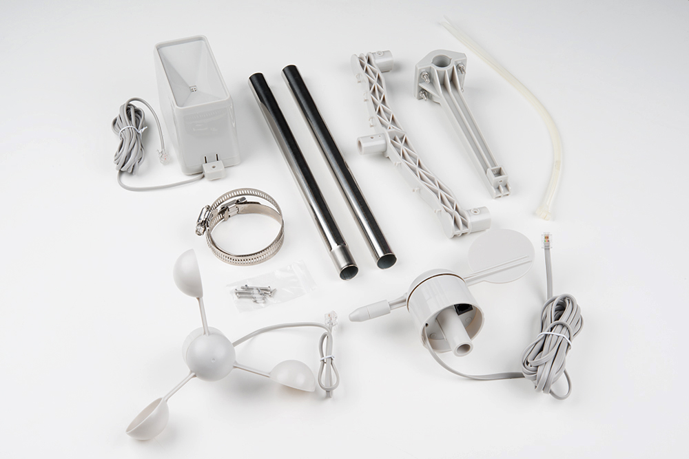
You should have:
- Two (2) metal tubes
- Three (3) sensors:
- rain gauge
- anemometer
- wind vane
- Two (2) gear clamps
- One (1) center mount armature
- One (1) side mount armature
- One (1) bag screws/nuts
- One (1) pack plastic zip ties
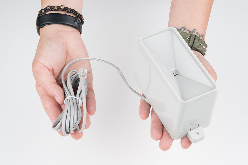
All of the sensors in the weather meter kit are passive components. This means you will need a voltage source in order to measure anything with them.
Each sensor is terminated with an RJ11 connector.
Rain Gauge
The rain gauge, as you may have guessed, measures rainfall. You sould get a rain gauge that looks similar to the image below.
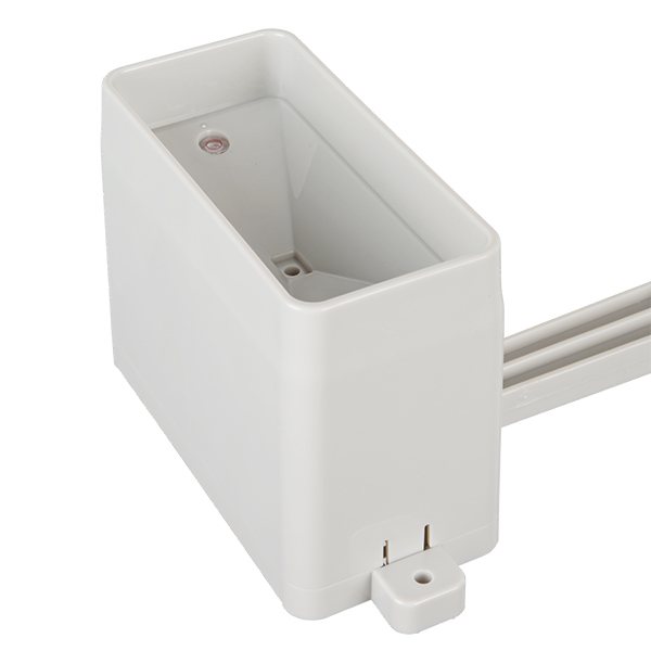
The sensor is a self-emptying tipping bucket collector. This means that for each 0.011" (0.2794 mm) of rain that falls in the sensor, the bucket will tilt, dumping the water out and closing a momentary contact.
The closure of the momentary switch can be measured using interrupt pins or a digital counter. The center conductors of the RJ11 connector are connected to the gauge's switch.
Anemometer
An anemometer measures wind speed.

The wind moves the cups on the anemometer, which in turn, rotate a enclosed magnet. The magnet closes a reed switch on each rotation, which is reflected on the output. You can measure this on the two inner conductors of the RJ11 connector (pins 2 and 3), using a digital counter or interrupt pins on your microcontroller. To convert this into a functional wind speed, use the conversion of 1.492 mph = 1 switch closure/second. For those in metric land, this is 2.4 km/h.
Wind Vane
The wind vane indicates the direction that the wind is blowing.

While you'd think think this would be a simple thing to represent with electronic components, this is actually the most complex gauges of the three. Internally on the vane are eight switches, each with their own unique resistor.
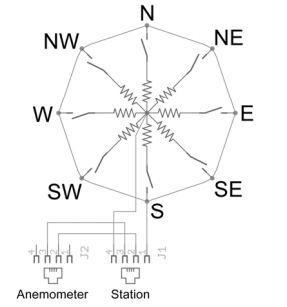
As the wind vane rotates, a magnet closes the reed switches, and may close two at a time due to their proximity to each other. With the use of an external resistor, a voltage divider can be created. Measuring the voltage output with an analog-to-digital converter on your microcontroller allows you to determine the direction the wind vane is pointing.
As the voltage output will depend on the value of the external resistor used, there is not one common conversion function. For an example of how to calculate this, please reference the datasheet linked in the Resources and Going Further for the meters.
Since the values outputted by the wind vane are are based on degrees, you can, in theory, have any value represent any direction. However, we recommend having the value at degree 0 represent North for ease of use. There are also very tiny, barely-visible direction indicators on all four sides of the wind vane. If you choose different values to indicate directions, be sure to mark then accordingly. When installing and positioning your weather meters, ensure that any direction markings are pointed in the correct orientation.
Please note that the wind vane "points" in the direction from which the wind is blowing.