Weather Meter Hookup Guide
 Toni_K
 Introduction
Weather stations require specialized sensors to accurately measure and report on weather conditions. For all of your DIY weather project needs, we have the Weather Meters!
These meters allow you to measure wind speed, wind direction, and rainfall easily over RJ11 connections.
Required Materials
To follow along with this project tutorial, you will need the following materials:
- 1x Weather Meter kit
- 1x Phillips Head screwdriver
- 1x Flathead screwdriver (optional)
Suggested Reading
If you aren't familiar with the following concepts, we recommend checking out these tutorials before continuing.
Analog vs. Digital
Digital Logic
Data Types in Arduino
Reed Switch Hookup Guide
Hardware Overview
When you receive your meters, unbox all of the components, and ensure you have all of the necessary pieces.
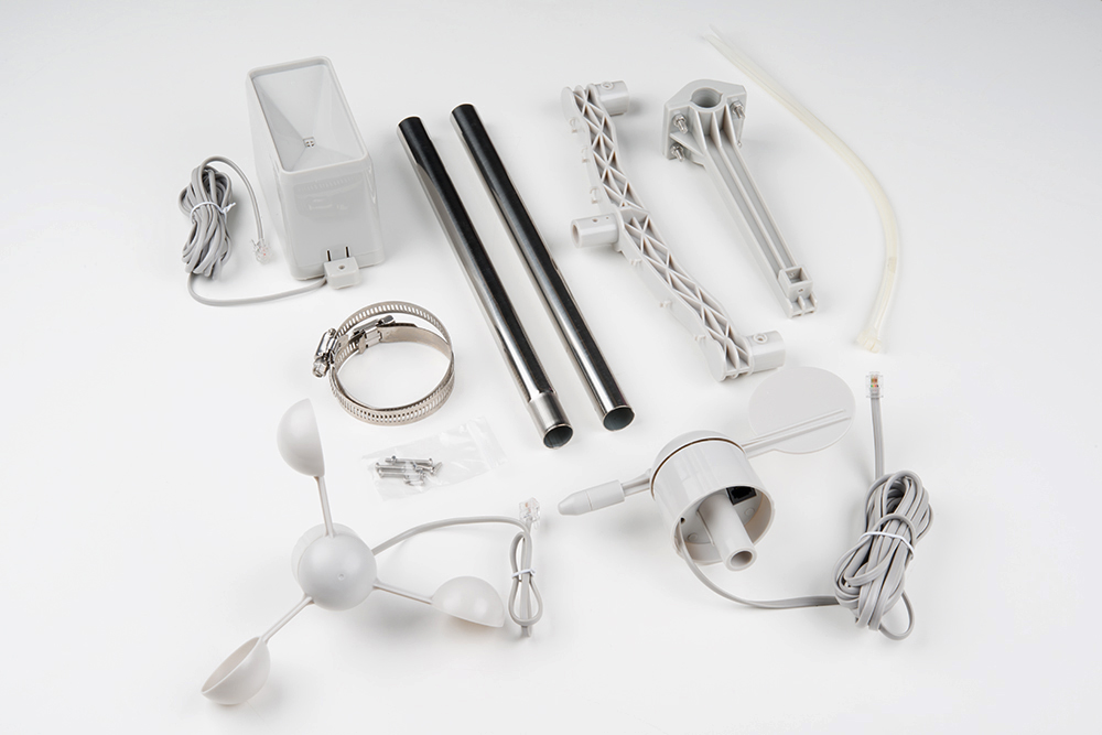
You should have:
- Two (2) metal tubes
- Three (3) sensors:
- rain gauge
- anemometer
- wind vane
- Two (2) gear clamps
- One (1) center mount armature
- One (1) side mount armature
- One (1) bag screws/nuts
- One (1) pack plastic zip ties
All of the sensors in the weather meter kit are passive components. This means you will need a voltage source in order to measure anything with them.
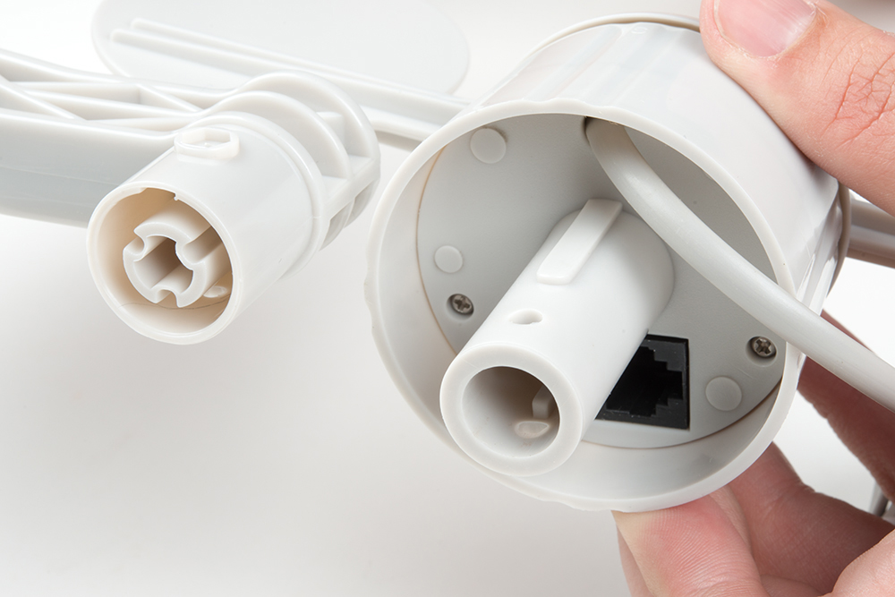
Each sensor is terminated with an RJ11 connector.
Rain Gauge
The rain gauge, as you may have guessed, measures rainfall. You sould get a rain gauge that looks similar to the image below.
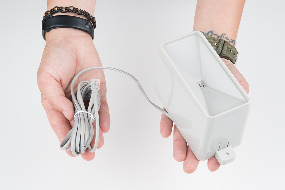
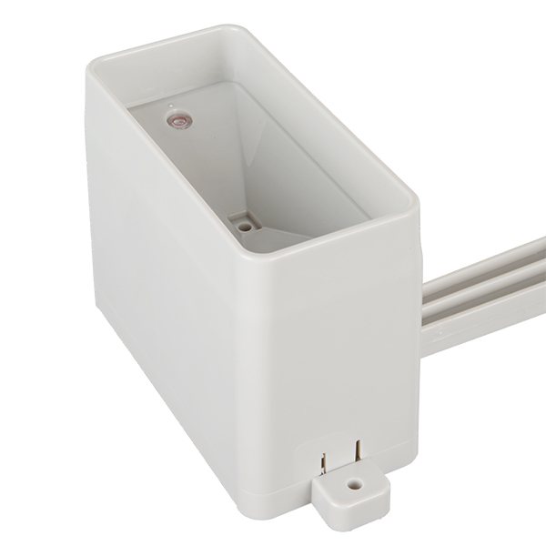
The sensor is a self-emptying tipping bucket collector. This means that for each 0.011" (0.2794 mm) of rain that falls in the sensor, the bucket will tilt, dumping the water out and closing a momentary contact.
The closure of the momentary switch can be measured using interrupt pins or a digital counter. The center conductors of the RJ11 connector are connected to the gauge's switch.
Anemometer
An anemometer measures wind speed.

The wind moves the cups on the anemometer, which in turn, rotate a enclosed magnet. The magnet closes a reed switch on each rotation, which is reflected on the output. You can measure this on the two inner conductors of the RJ11 connector (pins 2 and 3), using a digital counter or interrupt pins on your microcontroller. To convert this into a functional wind speed, use the conversion of 1.492 mph = 1 switch closure/second. For those in metric land, this is 2.4 km/h.
Wind Vane
The wind vane indicates the direction that the wind is blowing.

While you'd think think this would be a simple thing to represent with electronic components, this is actually the most complex gauges of the three. Internally on the vane are eight switches, each with their own unique resistor.
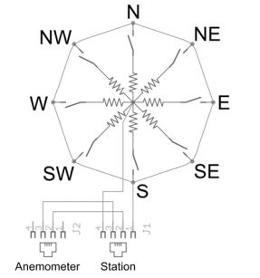
As the wind vane rotates, a magnet closes the reed switches, and may close two at a time due to their proximity to each other. With the use of an external resistor, a voltage divider can be created. Measuring the voltage output with an analog-to-digital converter on your microcontroller allows you to determine the direction the wind vane is pointing.
As the voltage output will depend on the value of the external resistor used, there is not one common conversion function. For an example of how to calculate this, please reference the datasheet linked in the Resources and Going Further for the meters.
Since the values outputted by the wind vane are are based on degrees, you can, in theory, have any value represent any direction. However, we recommend having the value at degree 0 represent North for ease of use. There are also very tiny, barely-visible direction indicators on all four sides of the wind vane. If you choose different values to indicate directions, be sure to mark then accordingly. When installing and positioning your weather meters, ensure that any direction markings are pointed in the correct orientation.
Please note that the wind vane "points" in the direction from which the wind is blowing.
Hardware Assembly
The weather meter is an easy kit to assemble -- there are only mechanical connections that need to be made.
Armature
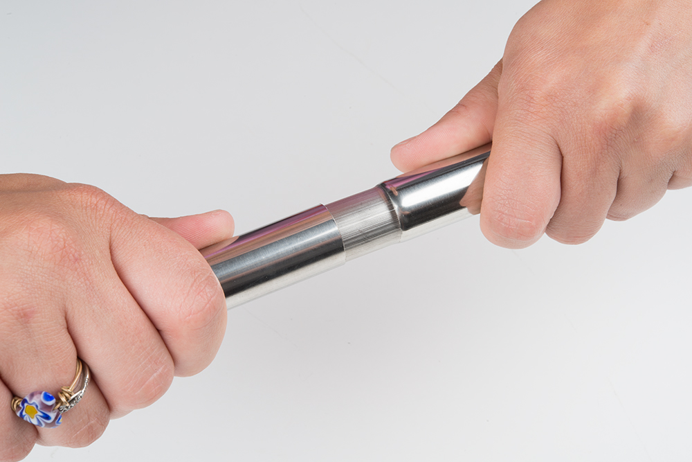
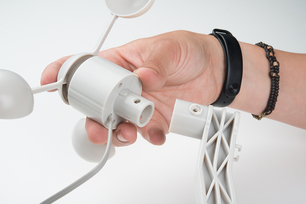
To begin, find the two metal tubes, and slide them together.
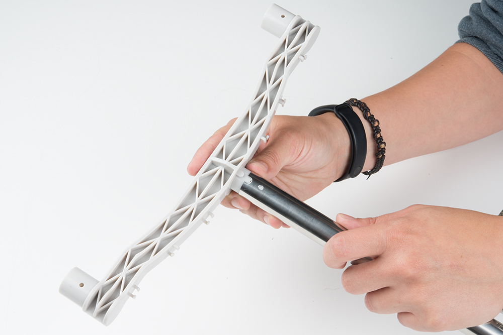
Next, add the armature to the top of the tube set. Make sure to line up the nub on the armature with the notch in the tube.
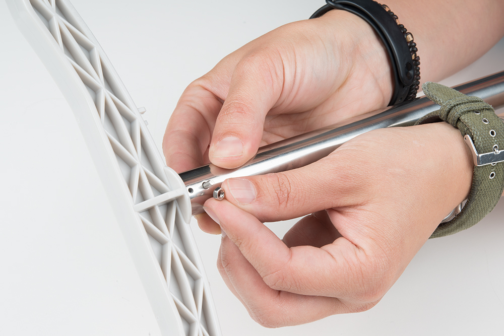
Use one of the included screws and nuts to lock it in place.
Anemometer
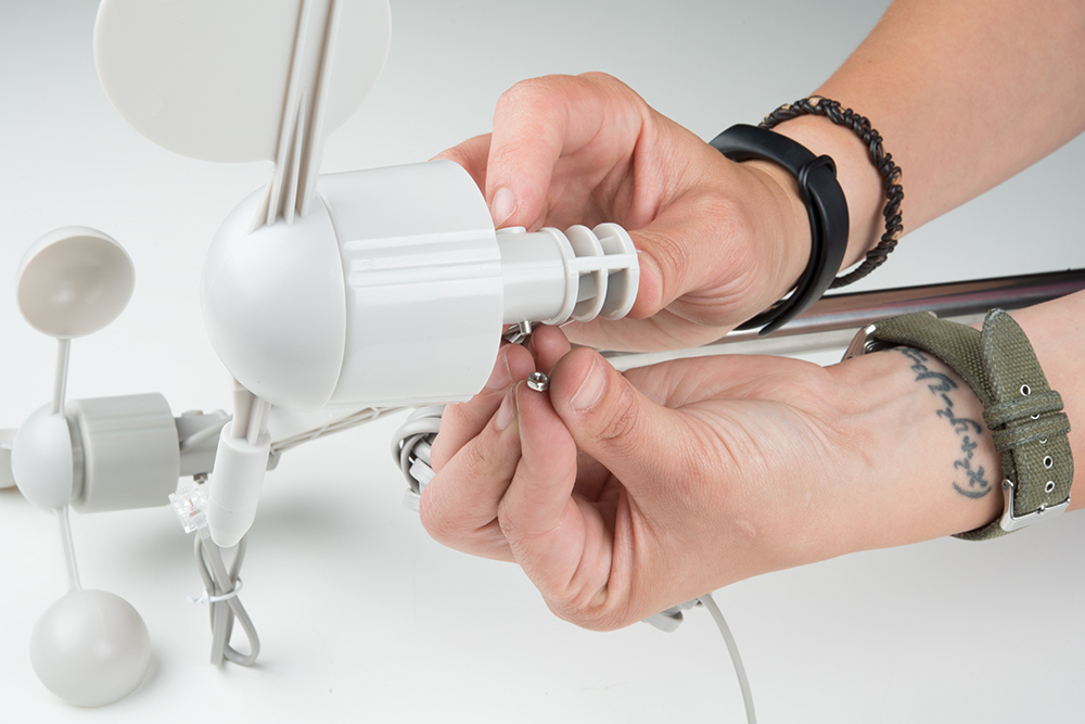
Next, we will mount the anemometer on one side of the armature.
The anemometer has a nub on it that matches notches in the armature. This will help secure the anemometer once attached and only allows the sensor to be mounted in one direction.
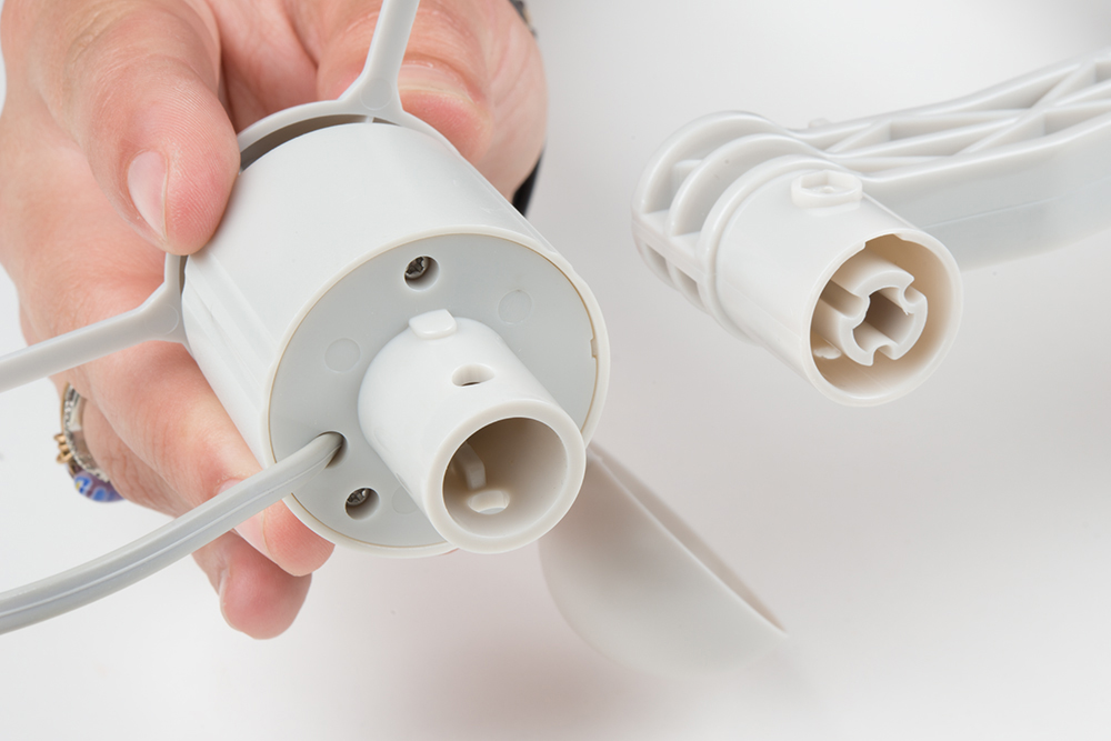
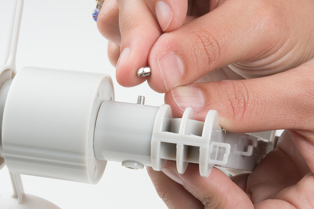
Slide the anemometer onto the armature until it locks in place.
Use an included screw and nut to lock the sensor in place (make sure these are tight).
Wind Vane
To attach the wind vane, you will follow the same procedure as installing the anemometer.
Line up the sensor and the armature, and push the wind vane into place.
Once again, use a screw and nut to secure the sensor in place.
Rain Gauge
To attach the rain gauge, we also need a secondary armature. This is used to keep the rain gauge away from the other sensors to ensure it can get an accurate measurement. If the rain gauge is mounted underneath the wind vane or the anemometer, they can block rainfall into the gauge or offset the readings due to runoff.
Attach the rain gauge armature to the metal tube using the attached screws and nuts. The two halves piece together with the metal tube in between. Once you have it located where the rain gauge will be clear of the anemometer and wind vane, tighten it into place.

Once again, the rain gauge has notches to ensure it mounts snugly on the armature.

Line these up, and push the rain gauge into place.
Using one of the remaining small screws, secure the rain gauge in place.

The rain gauge has two tabs with holes on either side. These can be used to mount the sensor on different surfaces such as rooftops or fences as well.
Wire Management
If you've gotten this far, congratulations! Now it's on to the easy part -- cable management. Luckily, this isn't nearly as difficult as some wiring projects.
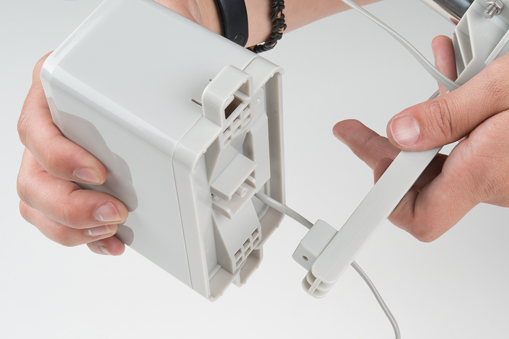
Unravel the wires from the anemometer and the wind vane. On the bottom side of the armature, you will see clips to hold these wires in place. Slide the wire from each sensor into those.

Once you have both of those cables plugged in, you will notice that the anemometer cable is much shorter than the wind vane. As we mentioned in the Hardware Overview, the anemometer switch conductors are shared between the anemometer and the wind vane. You will need to plug the anemometer cable into the wind vane.

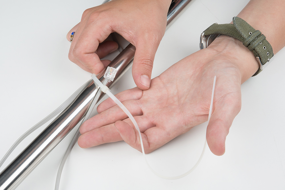
Run all of the remaining wires down the metal tubes, and use the included zip ties to secure them. This will prevent wind from yanking your wires out from your associated electronics.
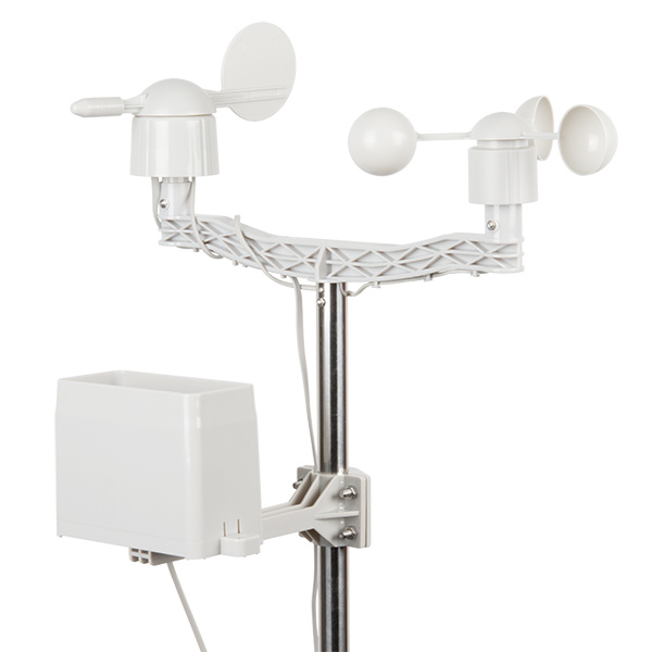
Success! You now have an assembled weather meter! Make sure your rain gauge is clear of the anemometer and wind vane, and didn't shift during assembly. Your weather meter will look similar to the image below.
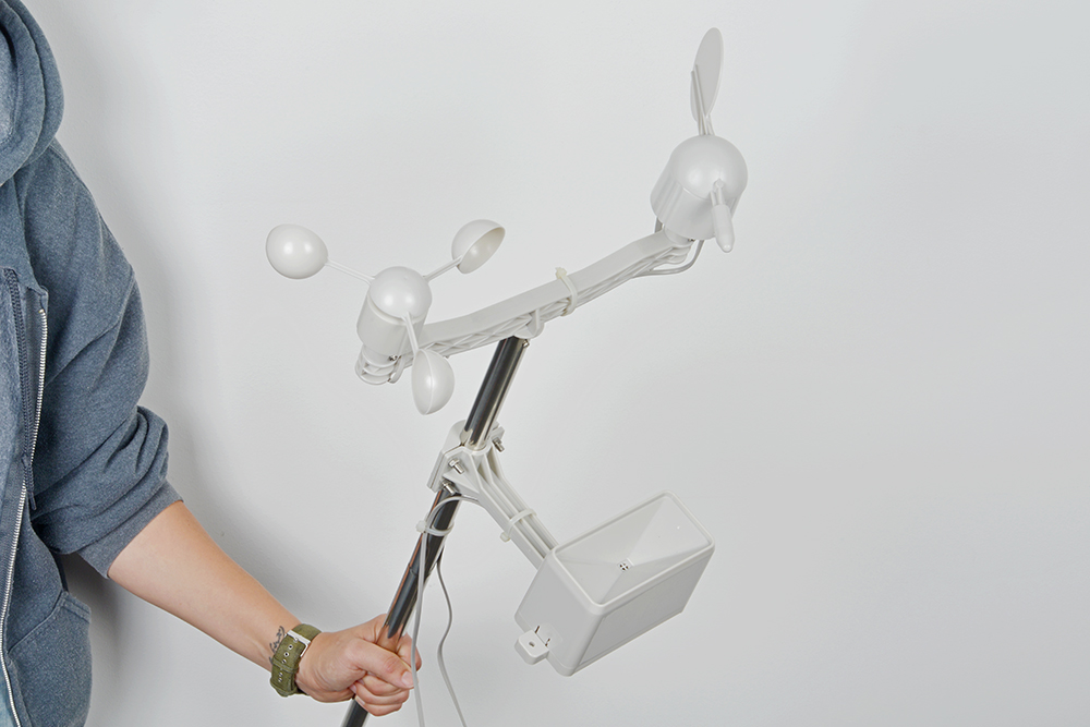
You can now mount this, attach it to various electronics, or just use it as an impromptu lightsaber in battle.
Mount the Meter (Optional)
Now that you've got your meter assembled, you need to place it somewhere with weather! You can use the included gear clamps to help mount and secure your meter.
To show a demonstration of how to use the gear clamp, we slid a gear clamp around our meter and a piece of PVC pipe. Then tighten the gear clamp using a flat head screw driver.

Keep in mind that there are many different ways to approach this problem. You will need to find a mounting solution that works specifically for your application.
Resources and Going Further
Now that you've successfully got your weather meter fully assembled, it's time to incorporate it into your own project!
For more information about the weather meter, check out the resources below.
- Datasheets
- SEN-15901 - Latest datasheet for the weather meters. The overall functionality is the same as SEN-08942. The only difference is the appearance of the rain gauge. If you are interested, click on this link!
- SEN-08942
Need some inspiration for your next project? Check out some of these tutorials that utilize the Weather Meters: