Variable Load Hookup Guide - Revised
 SFUptownMaker
Assembly
We recommend following this guide for easy assembly of the kit.
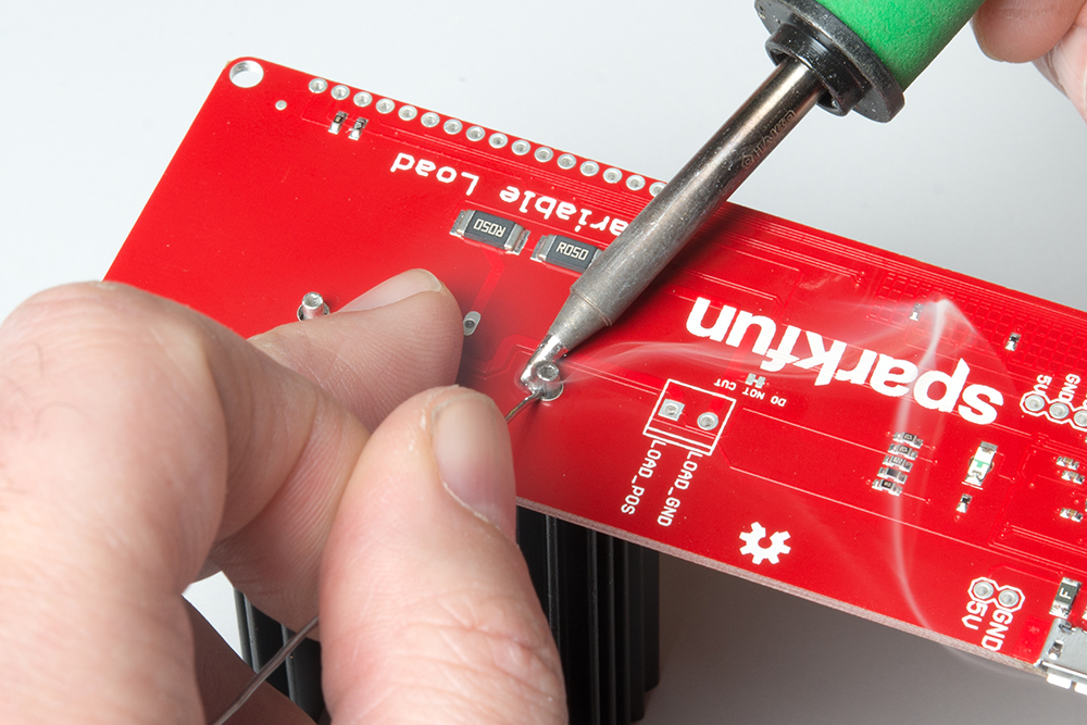
Install the Heat Sink
This may seem a little backwards, but there's a reason for this. We want to make sure that the hole in the heat sink is at the right height for the hole in the transistor to mate with it, and the heat sink is of fixed height, so we want to install it first.
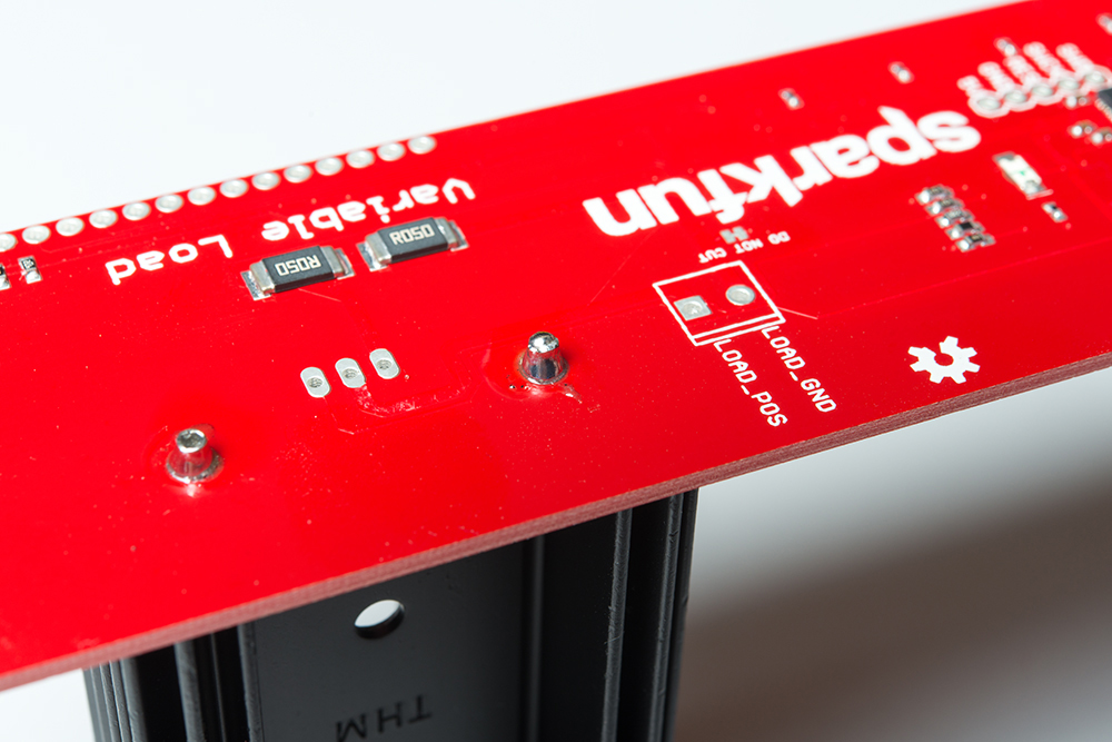
Note that soldering these nubs down takes patience and a willingness to get things pretty hot. If you don't heat the nubs up enough, the solder won't flow over them nicely and you'll get a gloppy, goopy cold solder joint. Heating the nubs takes time, of course, because they're attached to a heat sink! Persist and don't become discouraged if the solder won't flow onto the nubs at first. Give it lots of time. If you have one, a large, hoof-type soldering iron tip is the best bet for heating up the nubs for a good joint.
Note too that there are no exposed copper pads on the PCB. This is okay, as the solder will flow over the nubs and down through the holes, forming a tight fit.
Install the Terminal Block
This is a good time to install the terminal block. Notice which side of the board it is installed on, and the orientation of the terminal block with the silkscreen.

Soldering it down should be a fairly straightforward endeavor.
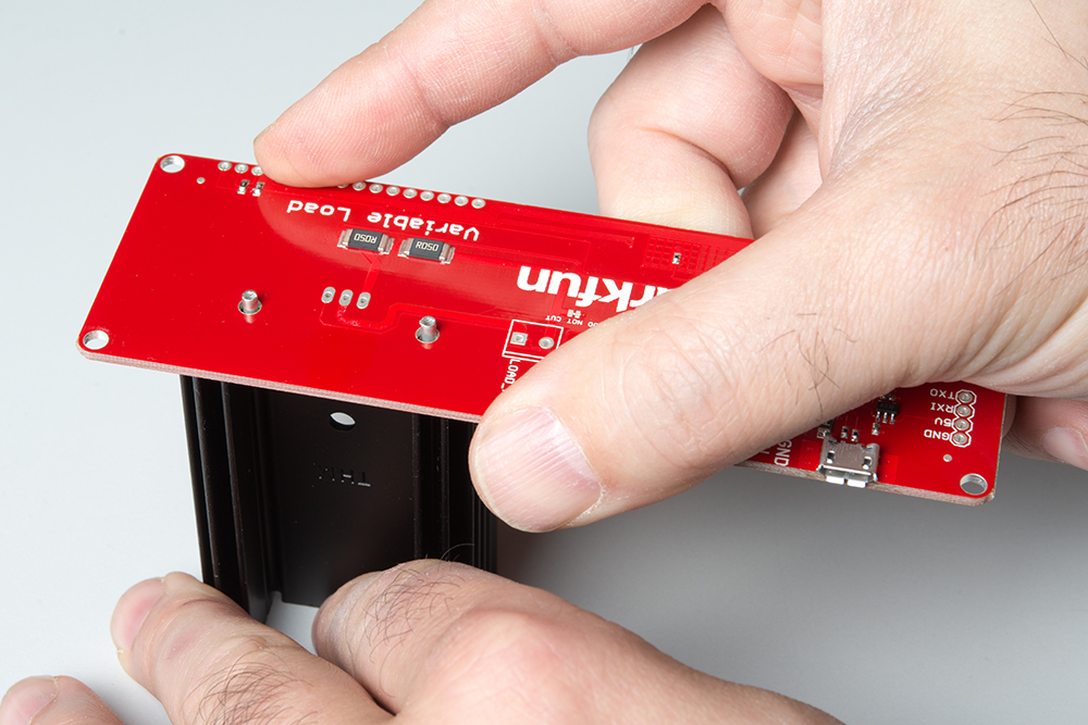
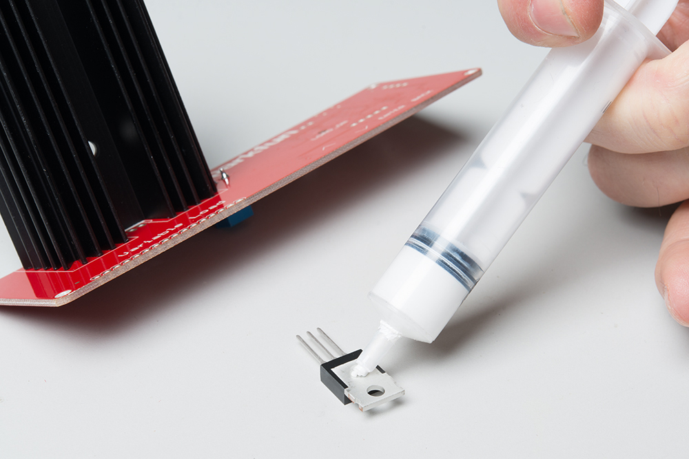
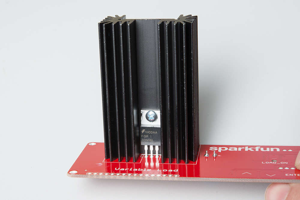
Install the Transistor On the Heat Sink
Apply a small amount of thermal grease to the back of the transistor. This will improve heat transfer to the heat sink.
Then, insert the 3/8" 4-40 machine screw through the hole in the transistor. Insert the legs of the transistor into the holes on the PCB and slide the pins down until the screw fits through the hole on the heat sink.
Thread the 4-40 nut onto the screw where it protrudes through the heat sink.
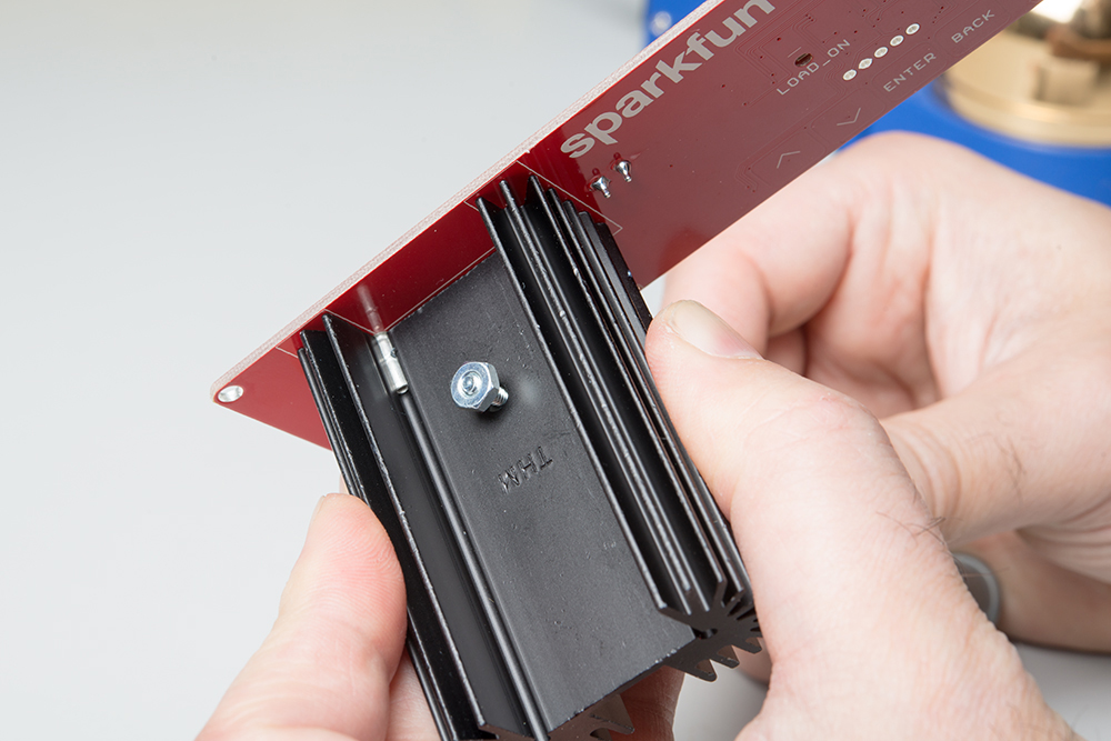
Tighten down the nut until it is snug. A screwdriver will help with this process. Do not overtighten the screw. It only needs to be a little tighter than finger tight. Then, flip the board and solder the transistor pins to the board.
Attach the standoffs to the corners of the board.
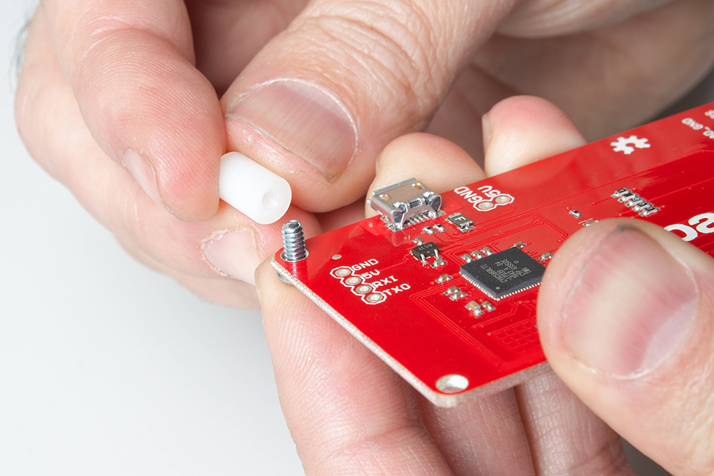
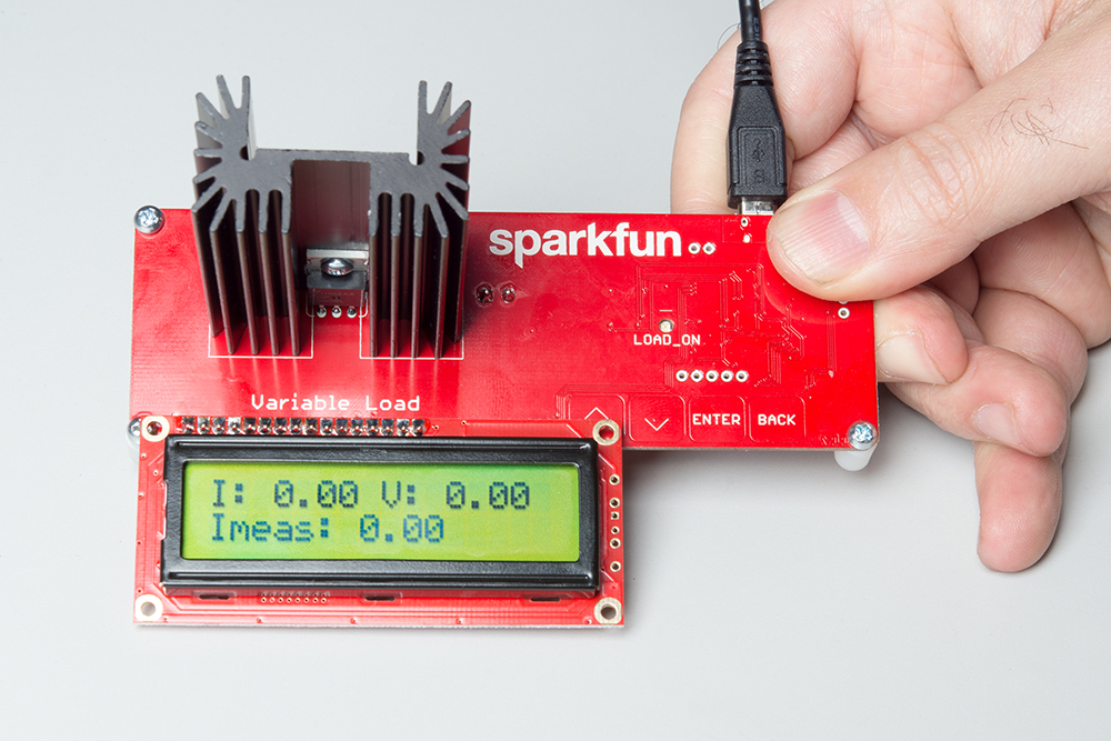
Finally, connect a micro-B cable to the Variable Load and your computer to get started.
Optional: Install the LCD Assembly
If you're going to use the Variable Load with the optional LCD, now is the time to attach it.
Start by installing the header on the LCD. Observe the image below for proper orientation.
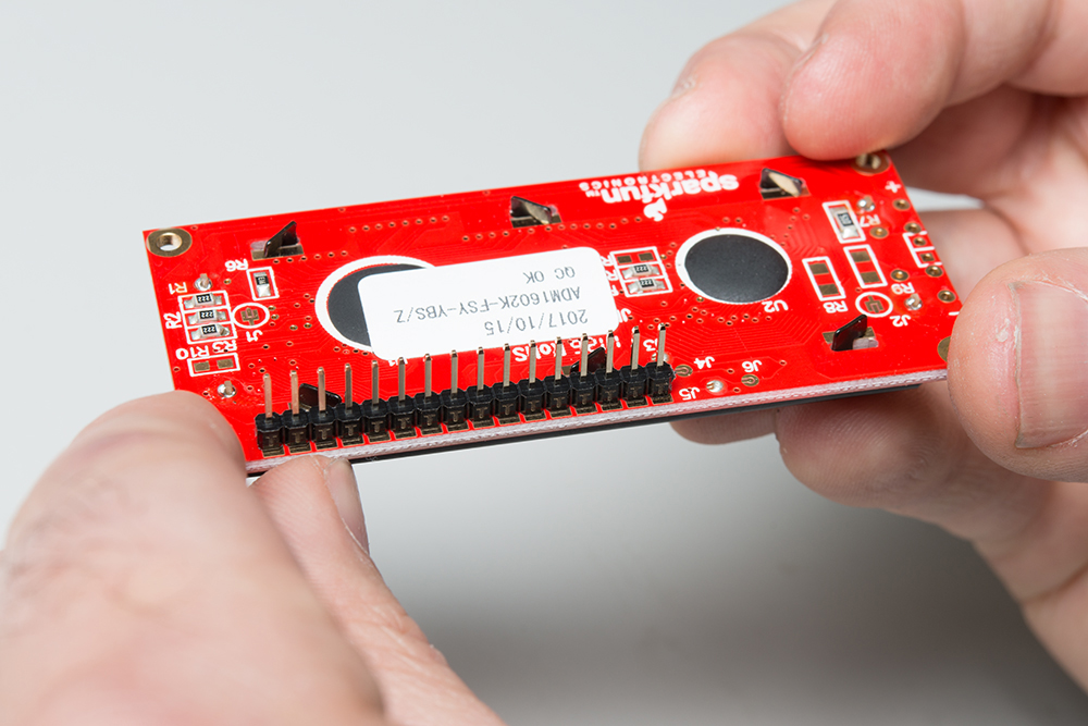
I like to tack down one pin first. Then melt the solder on that pin with one hand and use the other to make sure the header is at a right angle to the board. After soldering down all the pins, you can insert the header into the Variable Load board and repeat the process. Solder down the headers like the image below.
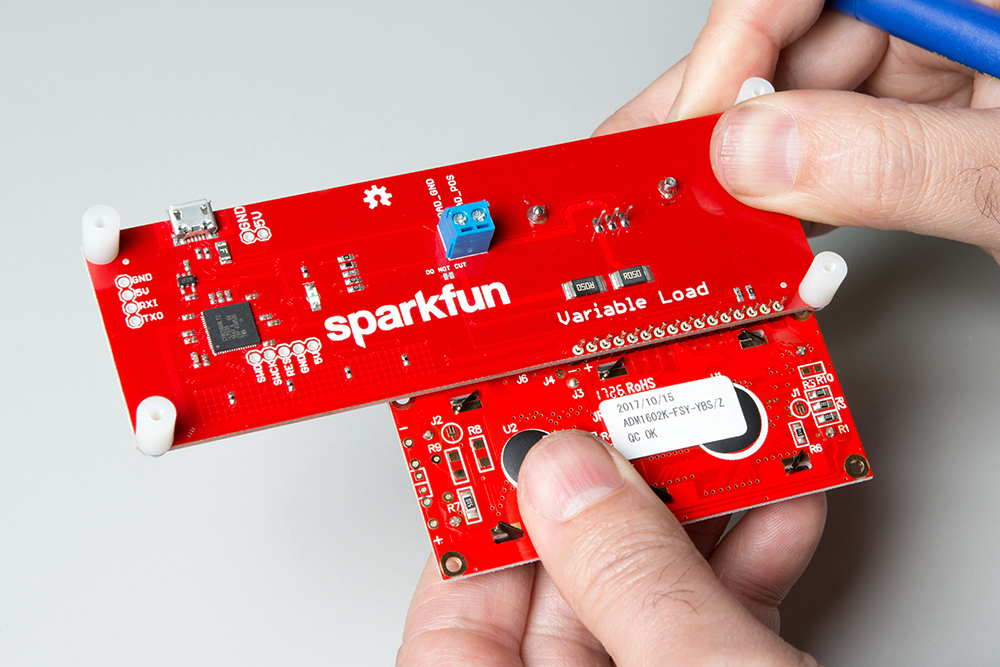
The LCD is now in place and should just work when powered up. Connect a micro-B USB cable to the Variable Load and your computer to get started.