Using the Arduino Pro Mini 3.3V
 jimblom
Assembly
The Arduino Pro Mini doesn't look like much when you first get it; it's as bare-bones as can be. We've left it up to you to solder headers or wires into the open through-holes. There are a few things to make you aware of though.
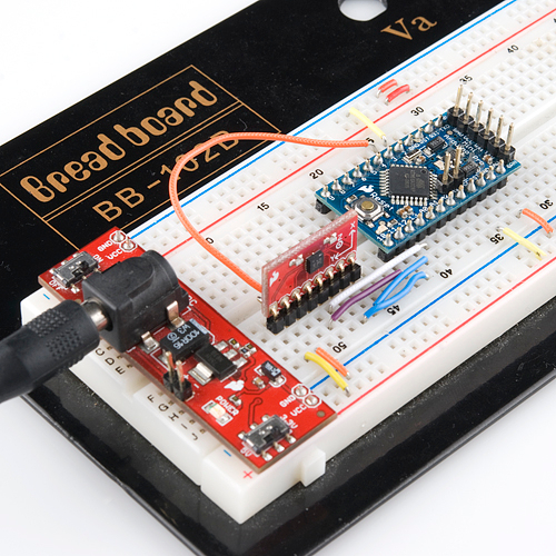
First, decide how you want to connect the FTDI Basic Breakout to the Pro Mini's programming header. The programming header is a row of six pins on the side of the board, labeled "BLK", "GND", "VCC", "RXI", "TXO", and "GRN". Since the FTDI Basic board is equipped with a female header, it's usually best to equip your Mini's programming header with mating male headers, either straight or right-angle.
The remaining assembly choices are up to you. There are many options; you could solder in male headers to make it breadboard-compatible, female headers to make it compatible with jumper wires, or just solder stranded-wire straight into the pins.
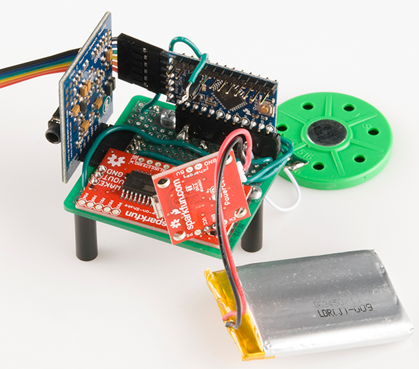
Versatility is what makes this board so great, and you can assemble it in whatever way makes the most sense for your project.