TSL2561 Luminosity Sensor Hookup Guide
This Tutorial is Retired!
This tutorial covers concepts or technologies that are no longer current. It's still here for you to read and enjoy, but may not be as useful as our newest tutorials.
 MikeGrusin
Connecting the Hardware
This guide covers connecting the TSL2561 Luminosity Sensor to an Arduino microcontroller. If you're using a different microcontroller, don't panic. Many microcontrollers have an I2C interface, and you can use this library, datasheet, and example code to help you write you own code.
Connection names
Breakout boards "break out" or connect the tinier pins on tiny components to larger connection points that we humans can deal with. (Robots are welcome to deal with the parts directly.) Breakout boards will also often include support components like resistors and capacitors that make the boards easier to use.
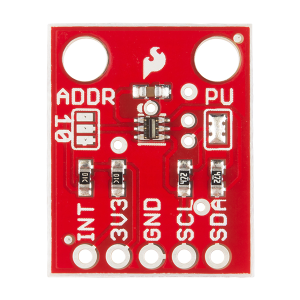
The TSL2561 Breakout Board breaks out five connections that we traditionally call "pins" but are actually holes that you can solder wires or header pins to.
You'll connect four of the five pins on the board to your Arduino. The four pins you need are labeled 3V3, GND, SCL, and SDA.
The fifth pin, INT is an optional interrupt signal which the TSL2561 can use to "interrupt" your microcontroller. You can set up the TSL2561 to automatically send an interrupt when it completes a measurement, or if a measurement goes above or below a certain level for a certain amount of time. This pin is not needed for the basic operation of the TSL2561.
Wiring up the board
You can use any method you like to make your electrical connections to the board. For this example, we'll solder on a five-pin length of male-male header strip, and use male/female jumper wires to connect the TSL2561 to an Arduino.
Step 1: Solder a 5-pin length of male-male header to the board. You can solder it to either side; the bottom is more useful for breadboards, and the top is more useful for jumper wires.
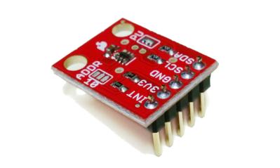
Step 2: There is no step 2.
Connecting to your Arduino
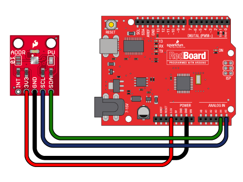
When you're done soldering, connect the 3V3, GND, SCL, and SDA pins to your Arduino. Different Arduino models use different pins for the I2C interface; use the following chart to determine where to plug everything in.
IMPORTANT: Connect the power pins (3V3 and GND) ONLY to a 3.3V supply. Larger voltages will permanently damage the part. Note that because I2C uses open drain drivers, it is safe to connect the I2C pins (DA and CL) to the I2C port on a 5V microprocessor.
| TSL2561 label | Pin function | Arduino connection | ||||||
| SDA | I2C data |
pin labeled SDA, or:
|
||||||
| SCL | I2C clock |
pin labeled SCL, or:
|
||||||
| GND | Ground | GND | ||||||
| 3V3 | 3.3V power supply | 3.3V (NOT 5V) | ||||||
| INT | Interrupt | Optional, leave disconnected unless you're using interrupts. |
Once you have the TSL2561 connected to your Arduino, we're ready to play with the software.