TSL2561 Luminosity Sensor Hookup Guide
This Tutorial is Retired!
This tutorial covers concepts or technologies that are no longer current. It's still here for you to read and enjoy, but may not be as useful as our newest tutorials.
 MikeGrusin
Tips and Tricks
Things to watch out for
Give it the right voltage: The TSL2561 will operate on voltages from 2.7V to 3.6V. We recommend operating it at 3.3V. Never connect the "3V3" header to voltages higher than 3.6V!. Note that it is safe to connect the SCA and SDL pins to an I2C port on a 5V Arduino, as the pullup resistors on the TSL2561 board will keep the voltage below 3.6V.
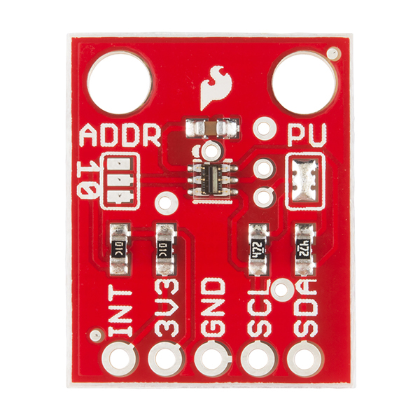
Changing the solder jumpers
Solder jumpers are closely-spaced pads on a printed circuit board that are joined by blobs of solder to create an electrical connection. The TSL2561 breakout board has two such jumpers; you can add or remove solder from these pads to alter the functioning of the board.
To remove the solder from a solder jumper, cover it with solder wick, and carefully heat it with a soldering iron. When the solder melts, it will be absorbed by the wick. Remove the wick before the solder cools so it doesn't stick to the pads. If you didn't get all of the solder on the first pass, give it another try with a clean section of solder wick. When you're done you should be able to see a broken connection between the pads. While doing this be careful not to overheat the board (let it cool off between attempts), or the copper pads may lift from the board.
Disabling the I2C pullup resistors (PU)
The TSL2561 communicates with a host microcontroller via a communications standard called "I2C" (for Inter-Integrated-Circut). I2C uses two wires, usually labeled SCL (Serial Clock) and SDA (Serial Data). To function properly, I2C requires a pullup resistor on each of those lines. The TSL2561 Breakout Board includes these resistors. They're enabled by default, but you can disable them by clearing the solder jumper labeled PU.
I2C allows you to have multiple devices connected to the same two lines (collectively called a bus). The pullup resistors allow the bus to function, but you should only have one set of pullup resistors per bus.
If you have just one I2C device (such as the TSL2561 Breakout Board) connected to your microcontroller, the board is already set up properly. You don't need to change anything.
However, if you wish to connect more than one device to the bus, you should ensure that there is only one set of pullup resistors enabled on the bus. You do this by disabling every set of pullup resistors except one. (It doesn't matter where the enabled resistors live; they can be anywhere on the bus.)
To disable the I2C pullup resistors, remove all of the solder from the jumper labeled "PU". This jumper has three pads; be sure to separate all of the pads from each other. Remember that you'll need to ensure that another set of pullup resistors are enabled somewhere on the I2C bus.
To enable the I2C pullup resistors (factory default), add solder to bridge both sides of the "PU" jumper to the center pad. There should be one large blob of solder when you're done. Remember that you should only have one set of pullup resistors enabled on the entire I2C bus.
Note that you should not operate an I2C bus without pullup resistors. Aside from not functioning properly, the internal weak pull-up resistors in a 5V Arduino will pull the bus to 5V which may damage the TSL2561.
Changing the I2C address (ADDR)
Every component attached to an I2C bus has a fixed address from 0 to 127. You can theoretically have a maximum of 128 devices on a single bus, but in practice you are limited to the options available for each part.
The TSL2561 supports three possible addresses: 0x29, 0x39, or 0x49. Practically speaking, this means you can have up to three TSL2561s attached to a single I2C bus.
Which address the part uses is controlled by the solder jumper labeled "ADDR". When there is no solder on this jumper, the TSL2561 will used the default address of 0x39.
To use one of the other addresses, add solder to bridge the center pad to ONE of the two side pads. If you bridge to the "0" side, the address will be 0x29. If you bridge to the "1" side, the address will be 0x49. Don't bridge both sides.
Remember that you will need to inform the software library of the correct part address. This is done when you call the library's "begin" function. Here's an example with three light sensors:
SFE_TSL2561 LightSensor1; // Declare a TSL2561 called "LightSensor1"
SFE_TSL2561 LightSensor2; // Declare a TSL2561 called "LightSensor2"
SFE_TSL2561 LightSensor3; // Declare a TSL2561 called "LightSensor3"

void setup()
{
  LightSensor1.begin();     // Initialize LightSensor1 to address 0x39
  LightSensor2.begin(0x29); // Initialize LightSensor2 to address 0x29
  LightSensor3.begin(TSL2561_ADDR_1); // Initialize LightSensor3 to address 0x49
}
Note that in the begin() function, you can use:
- Nothing (empty parenthesis) for the default address (0x39)
- One of the existing address numbers (0x29, 0x39, 0x49)
One of the following predefined address names:
TSL2561_ADDR (0x39)
TSL2561_ADDR_1 (0x49)
TSL2561_ADDR_0 (0x29)