TSH82 Configurable OpAmp Hookup Guide
 Pete-O
Hacking the Board
Changing Gain or Bandwidth
By this time, you’ve probably asked yourself about those two missing components. “What’s up with that? Did I get a bum board?” Nope, those footprints are intentionally left open for you to change the circuit behavior. Primarily, we’re talking about augmentations of the inverting configuration, as achieving similar results otherwise would require replacing parts; do-able, but more work and probably not necessary.
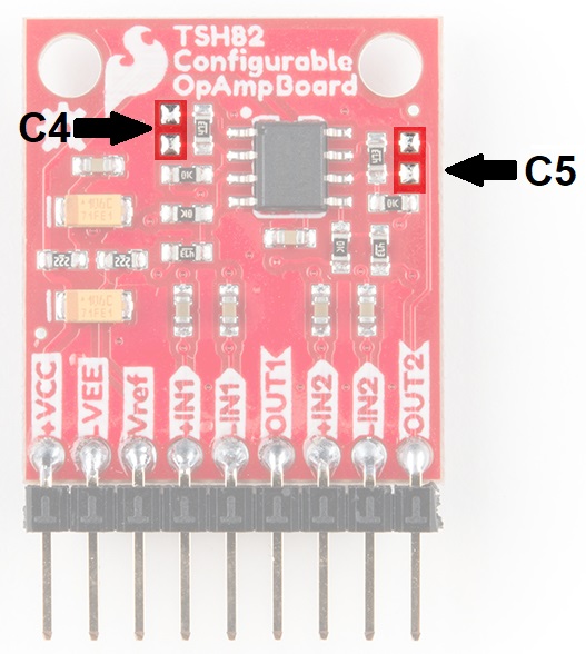
In the schematic, the parts are shown as C4 for stage one (on the left) and C5 for stage 2 (on the right).
There are two easy things you can change about the circuits’ behavior using the C4 and C5 footprints. First, you can alter it’s high frequency cutoff by adding a capacitor, as calculated from
where f is the desired cutoff frequency, and C is capacitance in farads. If you’re working with lower-frequency signals and you’re concerned about high-frequency noise, this is an addition you might consider.
The second thing you can do is to reduce the gain in order to increase the bandwidth by placing a resistor instead of a cap. Gain is calculated from
where R is the new component. For example, if you place an additional 47k resistor it will reduce your gain by half (Av = 2.35), but it will increase your workable bandwidth to around 18MHz.
Dialing In your Reference
As described in the section on non-inverting functionality, you may have reason to move your reference voltage (Vref) around. The easiest way to do this is with a potentiometer with one end on -VEE, another on +VCC and the wiper on Vref (10k is a good choice). This puts the potentiometer in parallel with the 2.2k resistor divider that sets Vref natively and allows you to set the reference to any value easily.

The on-board reference voltage is heavily decoupled with tantalum and ceramic capacitors to keep noise low. But if you need it lower, you might consider using a dedicated voltage source as the reference instead of the 2.2k resistor divider provided. Just attach your source to -VEE (0V) and Vref (positive voltage).