TMP102 Digital Temperature Sensor Hookup Guide
 Alex the Giant
Hardware Connections
Connecting the TMP102 to an Arduino
Wiring the TMP102 is very easy! We recommend soldering six male headers to the breakout board. You can also solder wires to fit your application's needs.
Power
This board runs from 1.4V to 3.6V. Be sure to power the board from the 3.3V pin! I2C uses an open drain signaling, so there is no need to use level shifting; the 3.3V signal will work to communicate with the Arduino and will not exceed the maximum voltage rating of the pins on the TMP102.
Connections to the Arduino
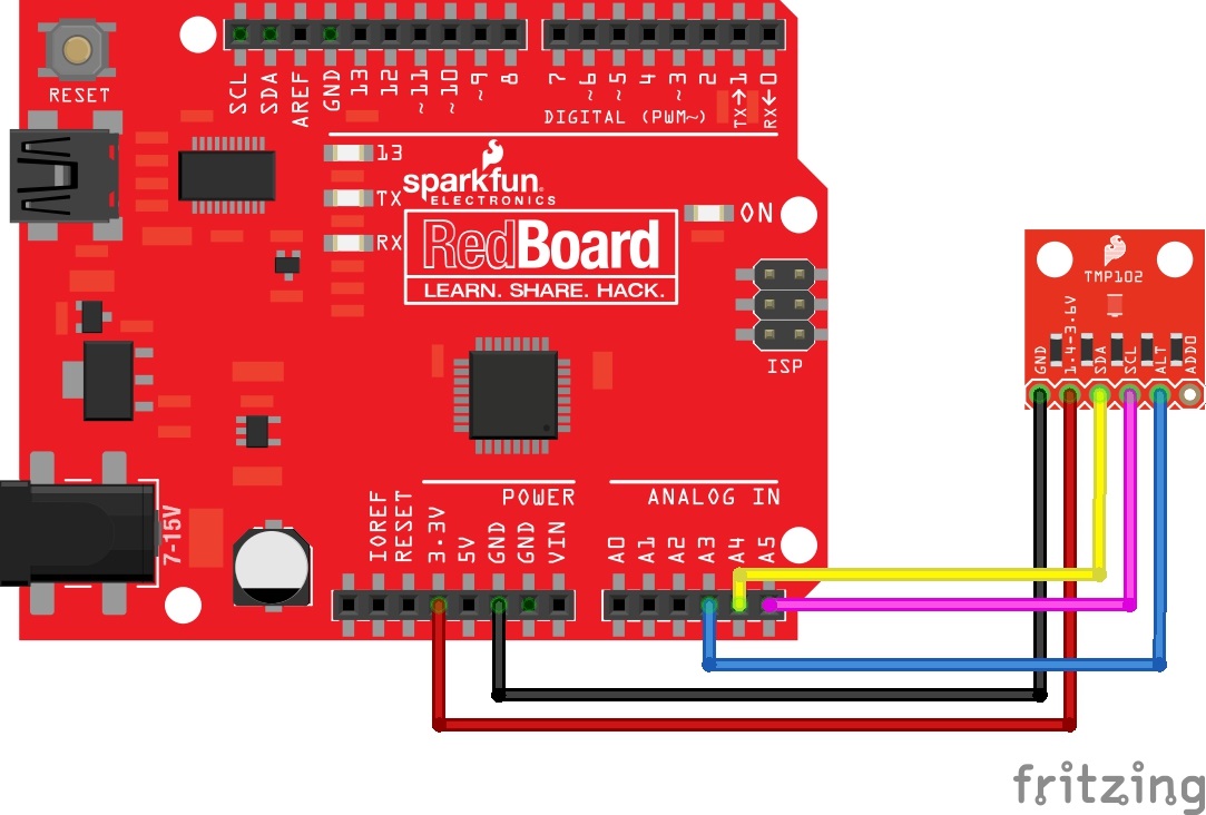
The TMP102 breakout board has six pins, however we'll only be using five of the pins in today's example. We'll be connecting VCC and GND to the normal power pins, two data lines for I2C communication, and one digital pin to see if there is an alert. If you're using a newer board that has SDA and SCL broken out, you can connect the SDA and SCL pins directly to those pins. If you're using an older board, SDA and SCL are pins A4 and A5 respectively.
- VCC → 3.3V
- GND → GND
- SDA → SDA/A4
- SCL → SCL/A5
- ALT → A3
This would looks something like this:
The only pin that we aren't using is ADD0, this pin is used to change the address of the TMP102. If you're using multiple TMP102s or another device that uses that address, you'll want to use this pin to change the address. The default address is 0x48. You can change the address by cutting the ADD0 jumper on the back of the board and connecting an external jumper wire to the following pins:
- VCC → 0x49
- SDA → 0x4A
- SCL → 0x4B