Tiny AVR Programmer Hookup Guide
ATtiny85 Use Hints
The ATtiny85 isn't your everyday Arduino IC. It packs a lot of punch for its small size, but there are some things it can't do.
On this page, we'll provide a quick overview of the ATtiny85 as it pertains to Arduino and the Tiny AVR Programmer.
Pinout
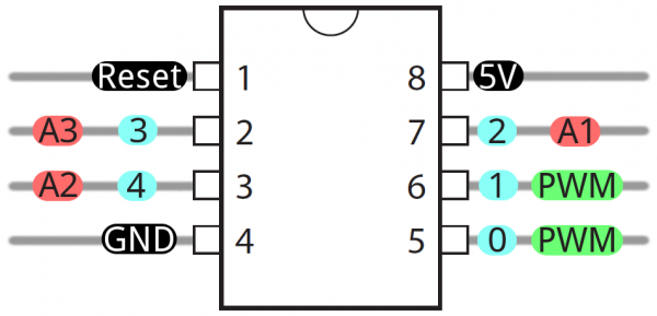
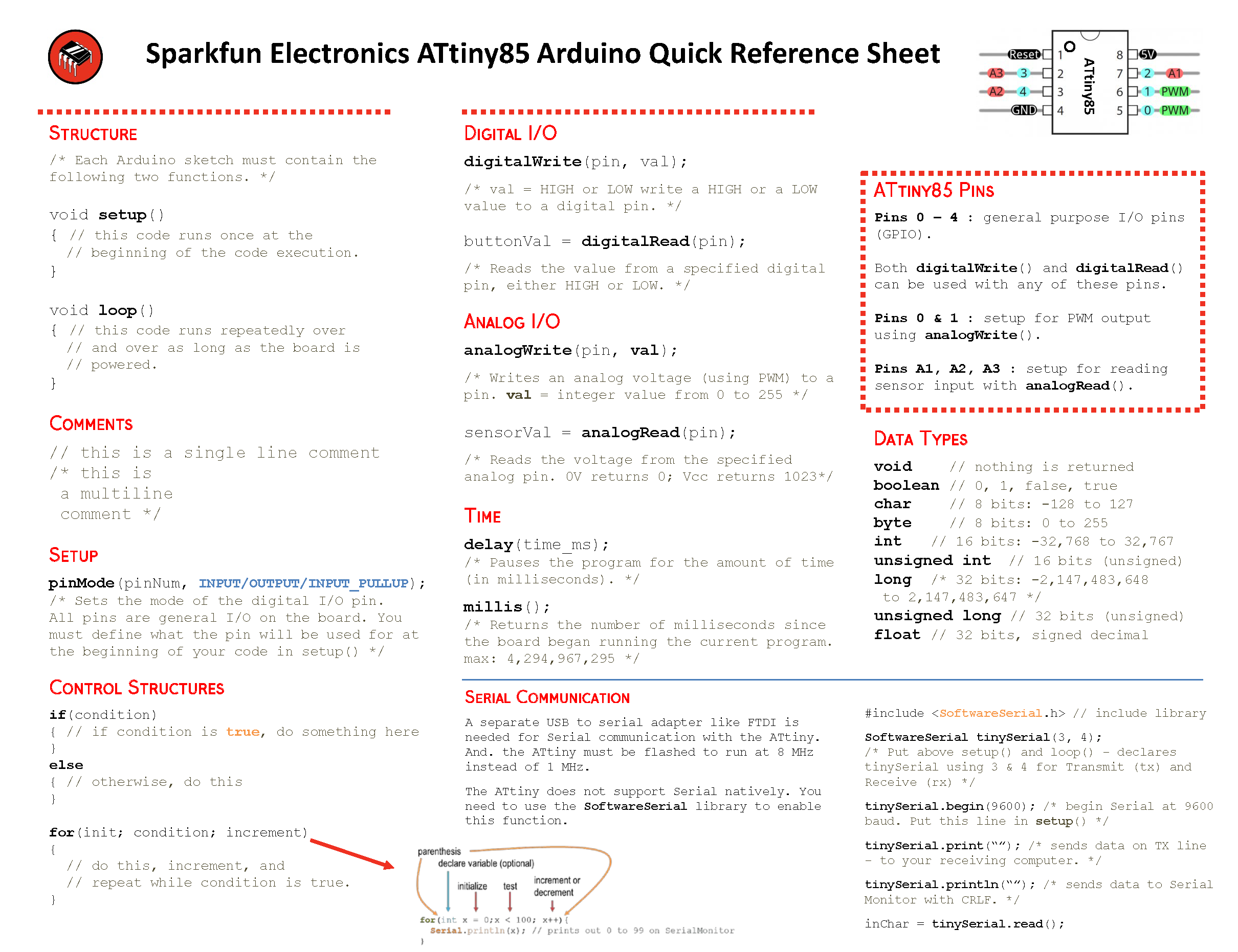
Just like any Arduino board, each I/O pin on the ATtiny85 is assigned a numerical identifier. These pins are documented on the board as well, but you can also refer to the image below if you forget.
Each of the I/O pins on the ATtiny85 are capable of digital input and output. Beyond that, some pins have special functionality.
Analog Input and Output
There are two analog outputs and three analog inputs. Use them just as you would with any Arduino board. Use analogWrite([pin], [0-255]) to do PWM output. This functionality is available on pins 0 and 1. For example:
language:c
int pwmPin = 0;

pinMode(pwmPin, OUTPUT);

for (int i=0; i<=255; i+=5)
{
  analogWrite(pwmPin, i);
  delay(5);
}
And use analogRead([pin]) to read an analog voltage between 0 and 5V, and turn it into a 10-bit representation of that voltage. Pins 2, 3, and 4 are capable of analog input, but, when using them as such, they should be referenced as A1, A3, or A2 respectively. For example:
language:c
int pwmPin = 0;
int analogInPin = A1;

pinMode(pwmPin, OUTPUT);
pinMode(analogInPin, INPUT);

int analogIn = analogRead(analogInPin); // Read analog voltage on pin 2 (A1)

analogWrite(pwmPin, analogIn / 4); // Output analog reading to dimmable LED
If you need to reset the chip, simply use the erase command with the Tiny AVR or Pocket AVR Programmer via command line to get it back to its previous state. Uploading code with the Arduino IDE will not be enough. Here is an example using the fuse bit settings for the LilyTwinkle's ATtiny85:
avrdude -c usbtiny -b 19200 -p t85 -v -e -U lfuse:w:0xe2:m -U hfuse:w:0xdf:m -U efuse:w:0xff:m -U lock:w:0xCF:mNo Serial (UART). Yes SPI and I2C.
You may notice, on the listing of special pin functions there are no UART RX's or TX's. That's because the ATtiny85 doesn't have a built in hardware UART. If you try to compile any Arduino code with Serial.begin(9600)'s or Serial.print()'s you'll get an error.
So you're out one of the more useful Arduino debugging tools. You can't print to the Serial Monitor. But the ATtiny85 does still have I2C and SPI, which are much more commonly used for sensor communication these days. Unfortunately, the Arduino libraries for these interfaces haven't yet been written for the ATtiny85, but there are some user contributed libraries around the web. USIi2c is an Arduino library which enables I2C on the ATtiny85.
There are other ATtiny85-focused libraries out there too. Like a Servo8Bit, a servo library.
Prototyping with the Tiny AVR Programmer
There's only so much excitement you can get out of dimming a single, yellow LED. You'll eventually want to branch out, and start connecting your tiny85 to other electronic components. There are a few ways to do this.
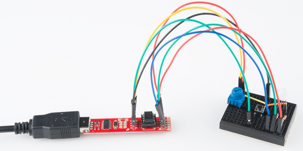
The easiest, least permanent prototyping route is to use the prototyping headers on either side of the socket. You can connect standard, male jumper wires to these pins, which can in turn be routed to breadboards or other components.
For more permanent projects, it's easy enough to gently remove the IC from the socket, and plug it into a PCB or breadboard. Eventually, once you've iterated enough on your sketch, this is probably where you'll want to go. Eventually you arrive at finished designs like the H2OhNo! or the LectroCandle.
Surface Mount ATtiny85 SOIC Packages
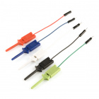
Trying to reprogram an ATtiny85 with a SOIC Package? There are a few ways to connect. The easiest would be to use the IC test clip and M/F jumper wires.
For more information, check out our tutorial on reprogramming ATtiny85's on the LilyTiny and LilyTwinkle.
Re-Programming the LilyTiny / LilyTwinkle
If the programming pins are broken out on a standard 2x3 ICSP header, you could also solder together the ISP pogo adapter to temporarily connect to the chip. Or you could grab a few alligator test leads or IC hook to individually connect each programming pin to the Tiny AVR Programmer's machine headers.
