The 970-HA-JOKES Payphone Project
 Nate
Nate 
WiFi
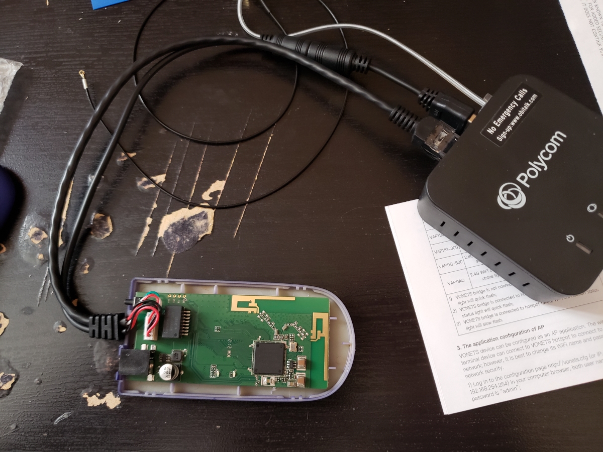
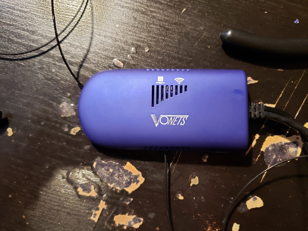
VOIP works but the phone would be located too far to run an ethernet cable. We convinced our friend who lives near the parking pad to allow us to use their WiFi ‘for a few days’. Thankfully, there are some off-the-shelf devices that are a simple WiFi to ethernet bridge. The VONETS VAP11G-300 fit the bill. Just plug it in and it’ll work, right? Unfortunately the metal tank of an enclosure reduced the PCB’s antenna reception terribly. If the phone was within ~10 feet of the WiFi access point, we could get reception but we need much further. Let’s change the antennas!
Of course I could have hung a couple rubber antennas off the back of the payphone enclosure, but that would completely ruin the experience. If you saw a payphone with antennas sticking out of the back, you’d know there was something going on. Where can we hide a pair of antennas so they still get reception? Hmm...
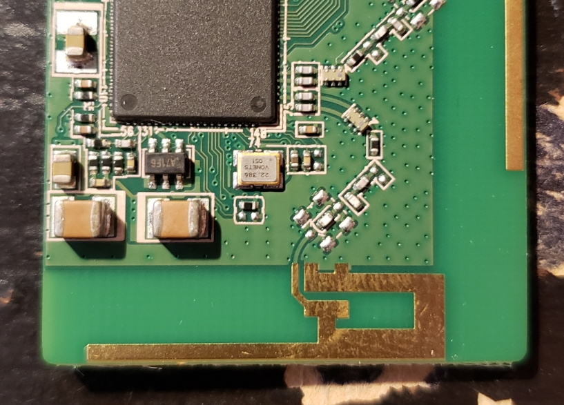
Above is the RF path connecting the IC to the PCB antenna.
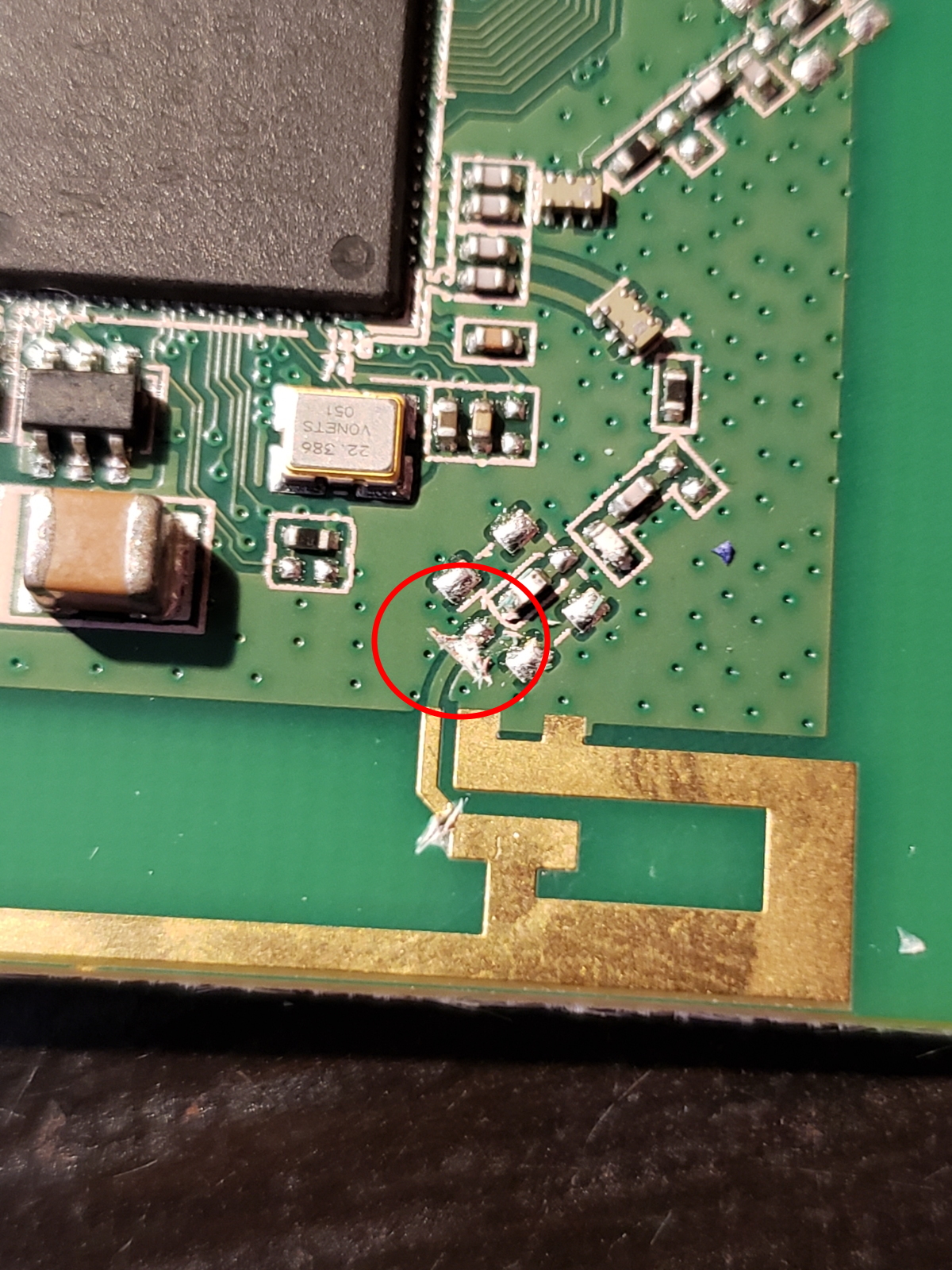
I made a cut to isolate the matching network from the PCB antenna. (The 2nd lower cut was unnecessary)
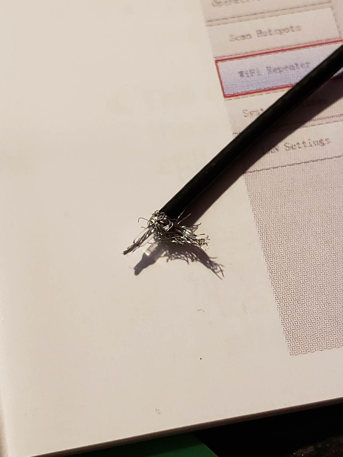
I cut the U.FL connector from a pair of 2.4GHz thin antennas and carefully stripped and exposed the signal pin and ground sheath.
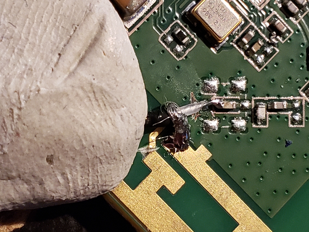
Sticky tack is my favorite tool and makes an excellent 3rd hand.
A bit of solder, and we’re connected. To give you a sense of minute scale, that’s my fingerprint in the sticky tack. These are all very small 0402 components.
You can see where this capacitor is located, there is an empty footprint for a U.FL connector. I could have hot-air reflowed a U.FL connector onto the board but it can be just as hard or harder to get four layer PCBs hot enough to rework a new connector on. Stripping and soldering was easier.
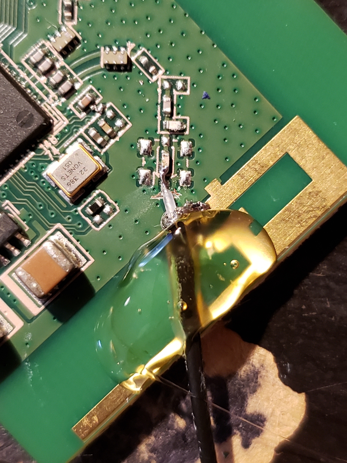
A blob of hot glue for mechanical reinforcement and we’re down one, with one to go!
Sticky tack. Sticky tack. 2nd RF path.
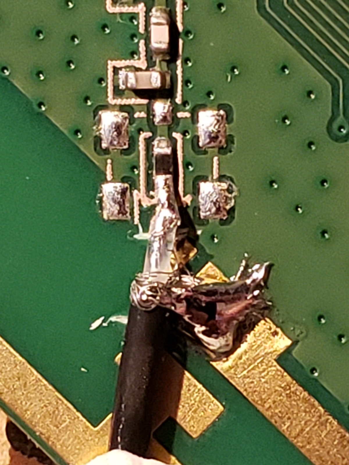
And we’re soldered! Note the fine hairs coming from the ground sheath. Before turning on the board I did a continuity test between the RF connection and GND to confirm there were no shorts.
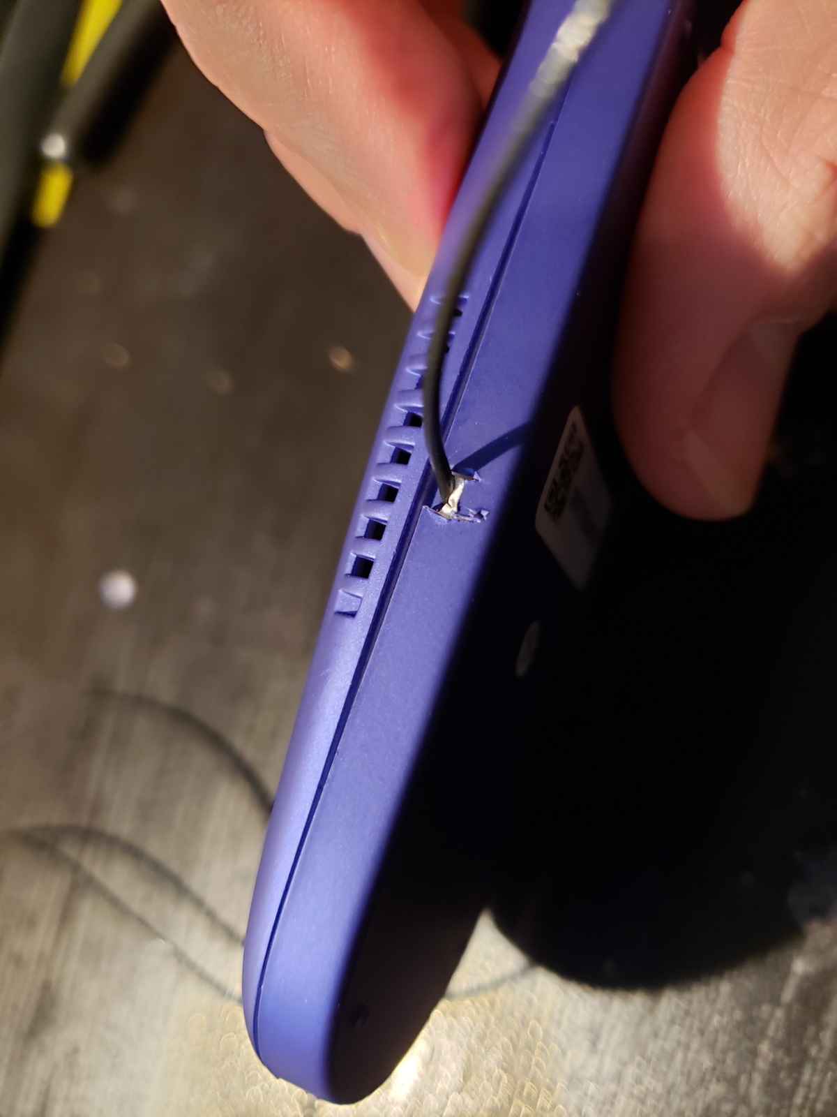
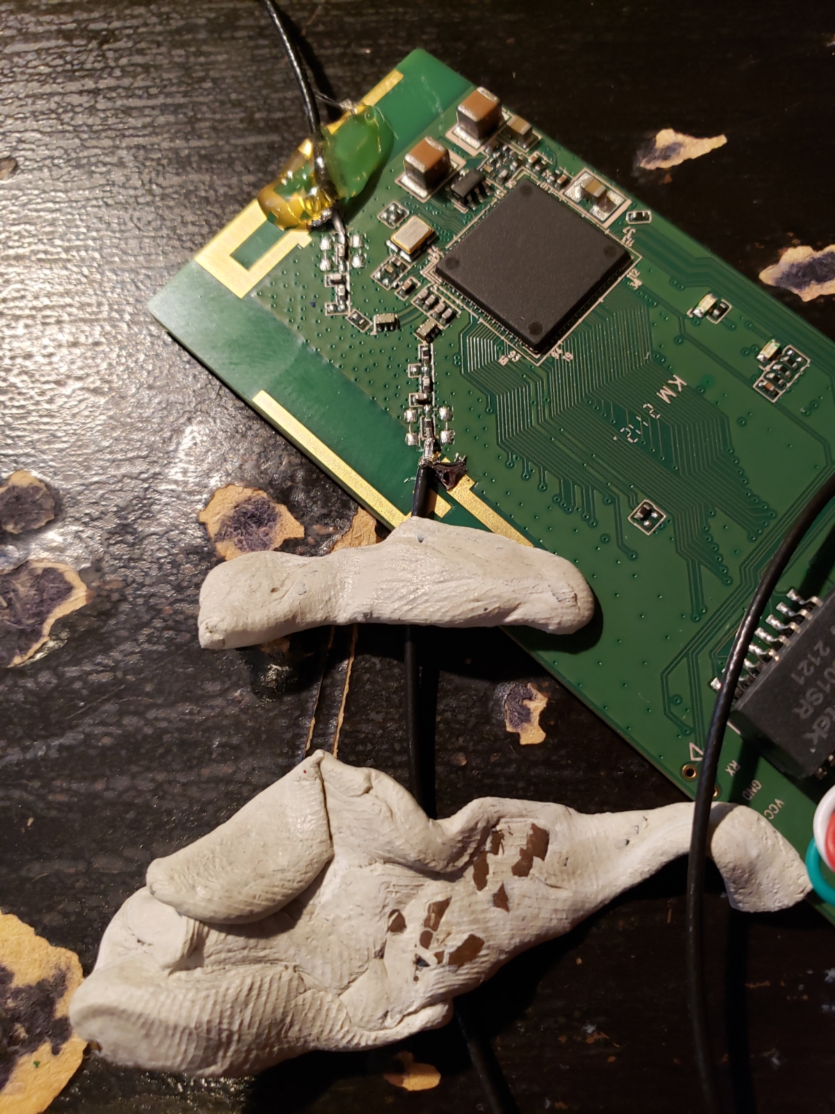
A quick and dirty enclosure modification allowed the thin RF cables to exit their respective sides of the enclosure.
It’s an ethernet WiFi bridge with aftermarket external antennas!
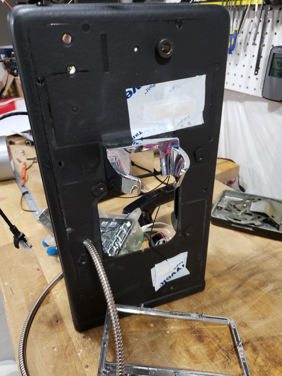
Above I’ve got the two antennas located and taped within the infographic areas. These are the areas that are covered by the paper and plastic describing how to use the phone. The infographics will cover the antennas while still allowing good RF reception.
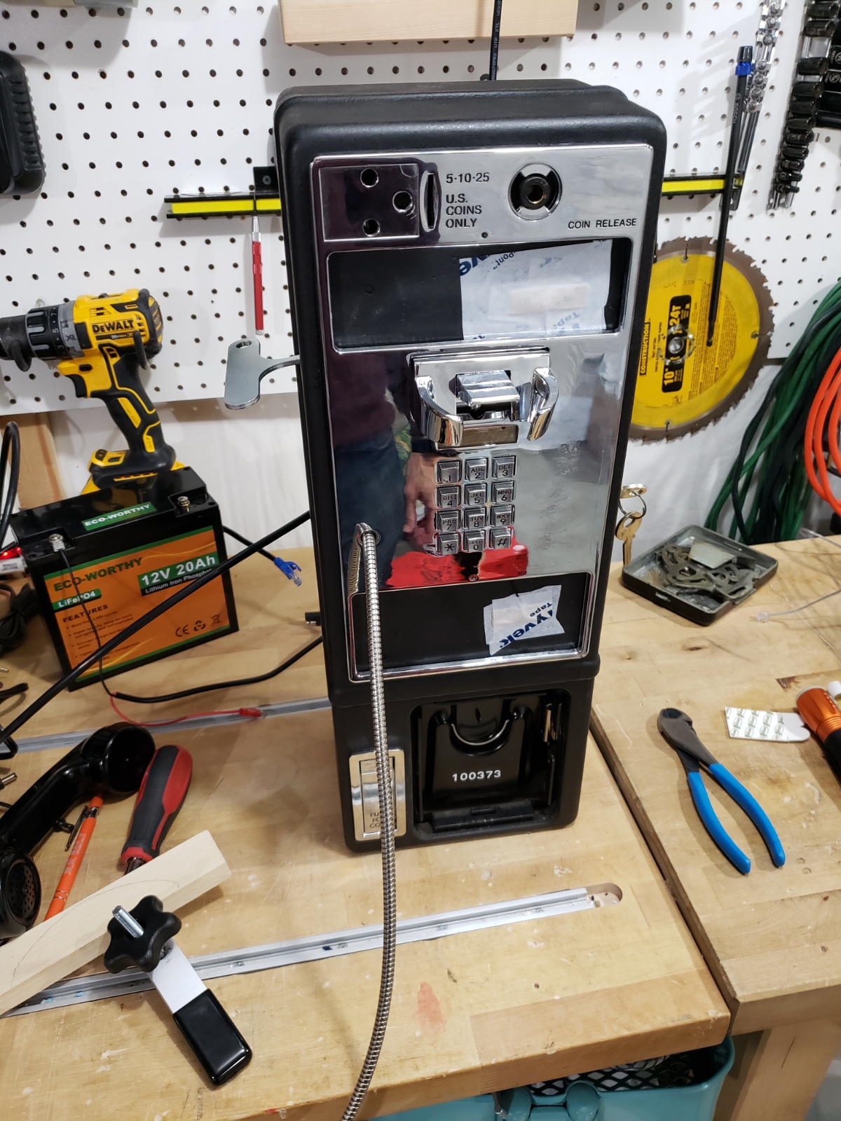
Front face attached showing where the antennas sit.
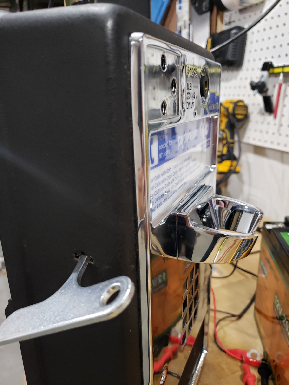
Above you can see the antennas protrude so little that even a very astute user would be hard pressed to detect them.
With the antennas located outside the enclosure, we gave it a try. A few field tests proved we’d get WiFi and VOIP access to our friend’s WiFi AP.