The 970-HA-JOKES Payphone Project
 Nate
Nate 
Bench Testing
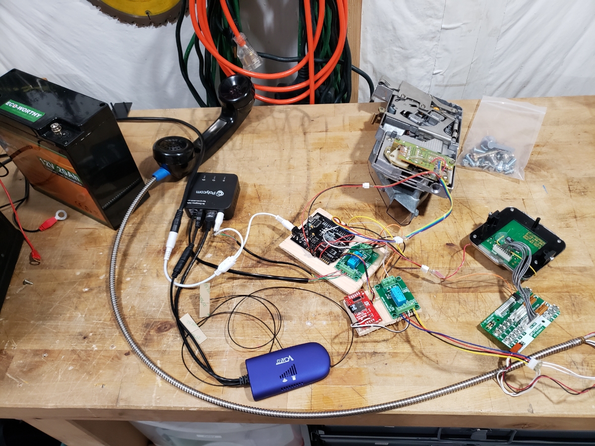
It lives!
In the end we have 8 pins to deal with via software:
- Analog pin for DTMF decoding
- GPIO for hook detection
- GPIO for VOIP call control
- GPIO for handset earpiece control
- GPIO x 3 for coin detection
- Qwiic connect to MP3 player
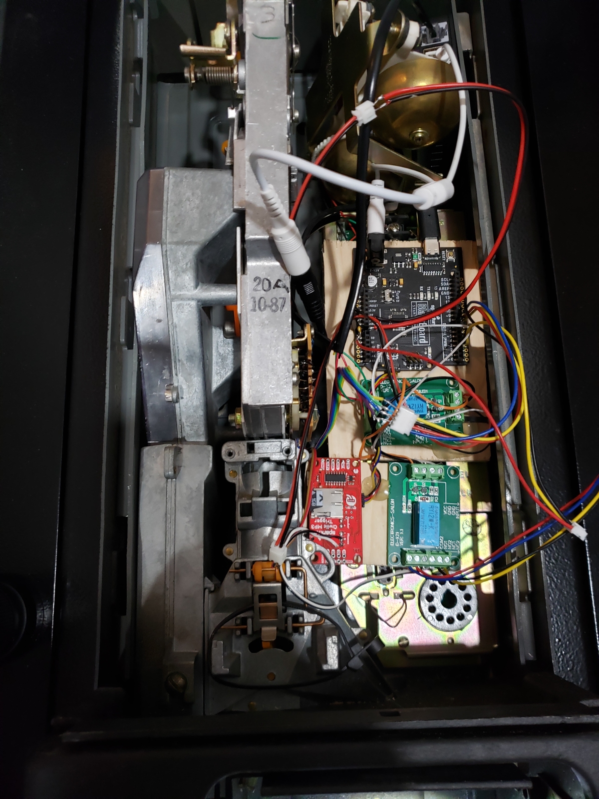
Here is everything placed inside the main housing. Some wood backboard with magnets glued on allowed the mess to be easily installed or removed.
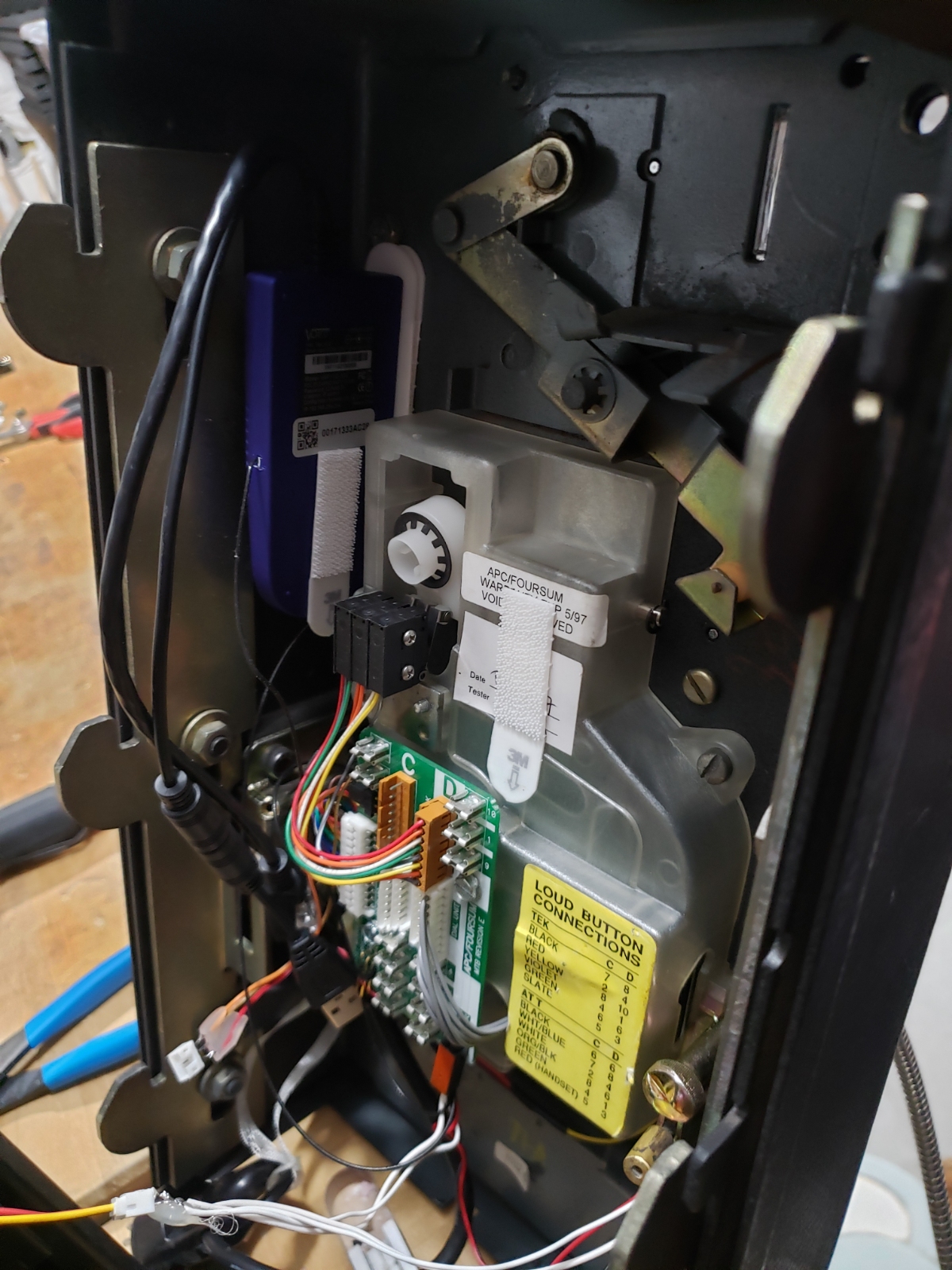
Above is inside the front face. You can see the large metal ‘coin return’ armature as well as the blue WiFi ethernet bridge. Down below you can see a few connectors with hot glue.
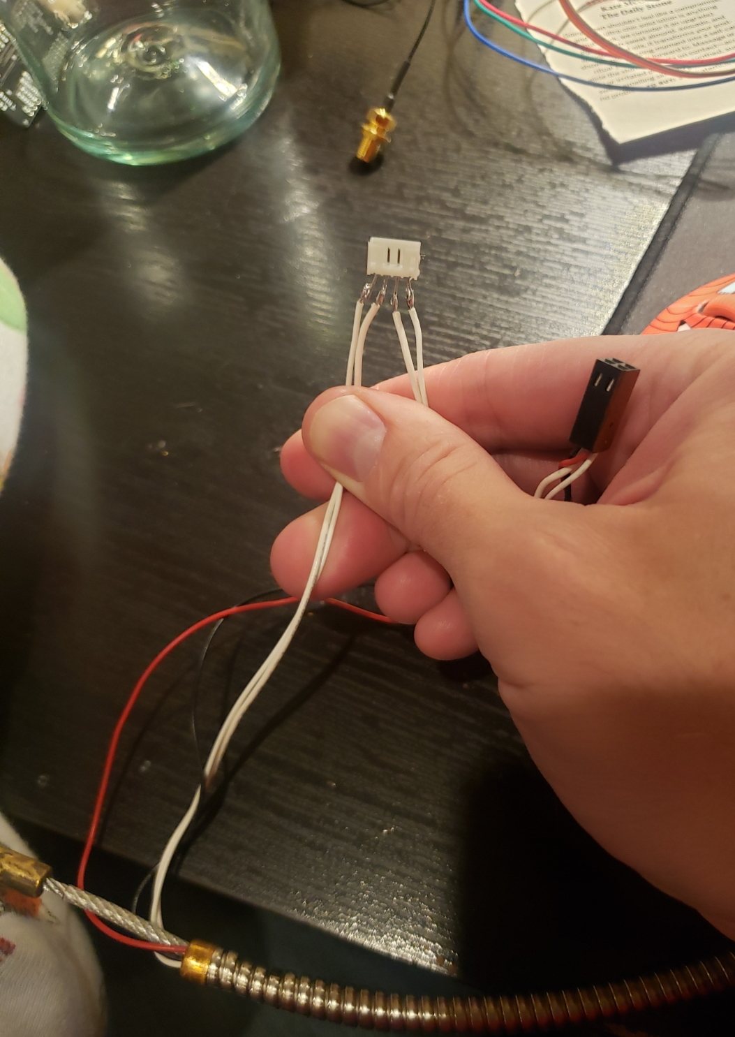
There were a few connections between the front face enclosure and the main housing. Normally these are contained in the single 11 pin circular connector but we needed 8 additional pins: 4 for earpiece man-in-the-middle, 3 for DTMF decoding, and 1 for detecting when the phone was on the hook. In order to allow the front face to be fully removed I soldered mating JST cable sets and reinforced and electrically isolated the connections with hot glue. In the above photo you can see the interruption of the handset earpiece wires.